Reference Information
2-10
Toshiba
27
RECORDING
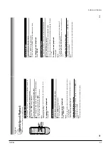
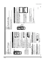
If a power failure occurs during the
timer pr
ogram r
ecor
ding
•
When a power failure has occurred,
“- -:- -
”
appears in the VCR display
. Since the
programmed contents have been cleared,
reset the clock and timer programming.
•
When power has failed for a short time, the
colon of the current time display blinks.
The
programmed contents are not af
fected. Reset
the clock.
Overlaps of the pr
ograms
If two timer programs overlap, the recording start
time of program 1 has priority over the recording
of
f time of program 2.
Program 1
(Start time)
Program 2
(Start time)
Overlapped portion
(not recorded)
Confir
ming the timer pr
ograms
Press
PROG
while timer recording.
The screen for confirming will appear
.
This screen can be sure only in the
T
imer
Recording mode.
Changing/cancelling the timer
pr
ograms
1)
If the
TIMER indicator is lit, turn the VCR on by
pressing
POWER
.
2)
With steps
2
to
9
, change the items.
T
o
cancel a program, select the program you
want to cancel in step
4
, and press
CANCEL.
The line is then cleared.
3)
Press
POWER
to return to the timer standby
mode.
Err
or indication
The blinking
“TIMER
” indicator appears in the
VCR display if you press both
TIMER
when:
––
a cassette is not loaded.
––
the loaded cassette has no safety tab.
In these cases, a recording can not be made.
E
n
D : PROG
SET UP
PRESET
PROGRAM
CH DATE O
n
OFF SPD
- - -/-- -:- - -:- - - - - -/-- -:- - -:- - -
- - -/-- -:- - -:- - -
- - -/-- -:- - -:- - -
- - -/-- -:- - -:- - -
2 5 8/30 9:30 10:00 SP
P M
P M
26
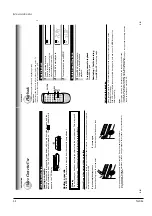
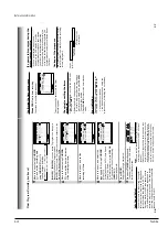
Auto Speed Select
If you are not sure the tape is long enough for
timer program recording in the SP tape speed,
set the recording tape speed to
“AUT
O
”.
Recording starts in the SP tape speed and the
VCR automatically selects the tape speed to
record the program to the end. If the tape length
is not long enough, the tape speed automatically
changes from SP
to SLP
.
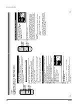
5
Move to the next using
CURSOR
( )
, and set the recording date
using
CURSOR (
▲
) or
(
▼
).
The date changes as follows:
[WKL
YSU]
…
[WKL
YSA]:
Y
ou can record
TV programs on the same
channel on the day and time every week.
[MO~FR]:
Y
ou can record
TV programs on the same channel on the
day and time Monday through Friday
.
6
Move to the next using
CURSOR
( )
, and set the hour and minutes
of the recording start time.
7
Move to the next, and set the
recording of
f time.
8
Move to the next, and select the
tape speed (SP) using
CURSOR
(
▲
) or
(
▼
).
For the tape speed
“AUT
O (Auto Speed
Select)
”, see below
.
T
o
set another program, press
CURSOR
( )
, and select the next line pressing
CURSOR (
▼
).
Repeat steps
4
to
8.
9
Press
PROG.
.
Now programming is completed.
10
Press both
TIMER
simultaneously
.
The power turns of
f and the VCR enters
the timer standby mode.
Notes
•
Make sure that the tape length is selected correctly
according to the tape used on the SET UP screen
(page 22).
•
When the SLP tape speed is selected and the tape
length is not sufficient to record the program to the
end, the program cannot be recorded to the end.
•
The picture will be distorted when playing the part
where the recording tape speed is switched from
SP to SLP with the Auto Speed Select feature.
Hi-Fi
STEREO
SAP
L
TIMER
T
imer Pr
ogram Recor
ding (contin
ued)
→
8/25
→
9/25
→
…
→
7/25
→
WKLY
SU
→
…
MO~FR
←
WKLY
SA
←
TIMER
REC
E
n
D : PROG
SET UP
PRESET
PROGRAM
CH DATE O
n
OFF SPD
- - -/-- -:- - -:- - - - - -/-- -:- - -:- - -
- - -/-- -:- - -:- - -
- - -/-- -:- - -:- - -
- - -/-- -:- - -:- - -
2 5 8/30 -:- - -:- - SLP
E
n
D : PROG
SET UP
PRESET
PROGRAM
CH DATE O
n
OFF SPD
- - -/-- -:- - -:- - - - - -/-- -:- - -:- - -
- - -/-- -:- - -:- - -
- - -/-- -:- - -:- - -
- - -/-- -:- - -:- - -
2 5 8/30 9:30 -:- - SLP
P M
E
n
D : PROG
SET UP
PRESET
PROGRAM
CH DATE O
n
OFF SPD
- - -/-- -:- - -:- - - - - -/-- -:- - -:- - -
- - -/-- -:- - -:- - -
- - -/-- -:- - -:- - -
- - -/-- -:- - -:- - -
2 5 8/30 9:30 10:00 SLP
P M
P M
E
n
D : PROG
SET UP
PRESET
PROGRAM
CH DATE O
n
OFF SPD
- - -/-- -:- - -:- - - - - -/-- -:- - -:- - -
- - -/-- -:- - -:- - -
- - -/-- -:- - -:- - -
- - -/-- -:- - -:- - -
2 5 8/30 9:30 10:00 SP
P M
P M
▼
▼
▼
Summary of Contents for W603C
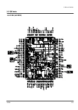
Page 20: ...Reference Information Toshiba 2 13 2 2 1 IC301 LA71072M 2 2 IC Blocks ...
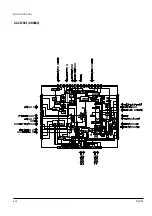
Page 21: ...Reference Information 2 14 Toshiba 2 2 2 IC501 AN3662 ...
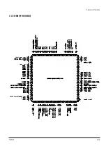
Page 22: ...Reference Information Toshiba 2 15 2 2 3 IC601 MN101D02X ...
Page 23: ...Reference Information 2 16 Toshiba MEMO ...
Page 25: ...Product Specifications 3 2 Toshiba MEMO ...
Page 56: ...Alignment and Adjustment Toshiba 5 11 Fig 5 21 Main PCB Top View VR501 Location for VR501 ...
Page 57: ...5 12 Toshiba Alignment and Adjustment MEMO ...
Page 59: ...Exploded View 6 2 Toshiba 6 1 Packing Assembly A702 A701 A702 Y101 Y102 UT01 ...
Page 63: ...Exploded View 6 6 Toshiba MEMO ...
Page 73: ...Replacement Parts List 7 10 Toshiba MEMO ...
Page 74: ...Toshiba 8 1 8 Block Diagram ...
Page 75: ...Block Diagram 8 2 Toshiba MEMO ...
Page 76: ...Toshiba 9 1 9 PCB Diagrams 9 2 9 3 9 3 9 3 9 1 Main 9 2 VFD 9 3 Jack 9 4 Key ...
Page 77: ...PCB Diagrams 9 2 Toshiba 9 1 Main ...
Page 78: ...PCB Diagrams Toshiba 9 3 9 2 VFD 9 3 Jack 9 4 Key ...
Page 79: ...PCB Diagrams 9 4 Toshiba MEMO ...
Page 82: ...Schematic Diagrams Toshiba 10 3 10 1 S M P S Power ...
Page 83: ...Schematic Diagrams 10 4 Toshiba IC601 VFD 10 2 Logic ...
Page 85: ...Schematic Diagrams 10 6 Toshiba 10 3 A V ...
Page 87: ...Schematic Diagrams 10 8 Toshiba 10 4 Hi Fi MTS ...
Page 89: ...Schematic Diagrams 10 10 Toshiba 10 5 TM Block Input Ouput ...
Page 90: ...Schematic Diagrams Toshiba 10 11 10 6 VFD ...
Page 91: ...Schematic Diagrams 10 12 Toshiba 10 7 Remote Control ...

