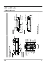
Reference Information
Toshiba
2-3
13
PREPARATION
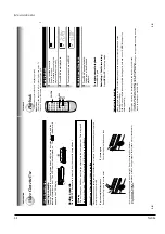
A
uto Set Up
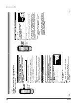
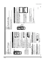
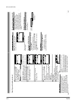
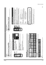
The VCR
’s clock and tuner channels are set automatically when the VCR is plugged into the AC outlet.
PREP
ARA
TION
Auto Set up
1
Plug the VCR into the
AC outlet
2
“AUT
O
” blink while the VCR automatically sets the clock
using the data broadcast by the local
TV stations.
While
“AUT
O
” is blinking, channel memory is also set
automatically
.
3
When
Auto set up has been completed, the VCR is on
standby mode.
Notes
•
It may takes several minutes during the
Auto set up
•
Press
CANCEL
on the remote control to cancel the auto set up.
CANCEL
12
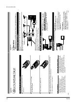
This set-up will enable you to:
–
watch an unscrambled or scrambled channel
while recording it.
–
record any channels through the cable box.
You will need to:
•
set
TV channel 3 or 4 to receive video signals.
(See page 1
1.)
•
set VCR channel to the output channel of the
cable box, and select a desired cable channel
on the cable box.
•
while the VCR is turned of
f or the
“VCR
”
indicator is not lit in the VCR display
, set
TV
channel to the output channel of the cable box.
This set-up will enable you to:
–
watch an unscrambled or scrambled channel
while recording it.
–
record an unscrambled channel while watching
another unscrambled channel (only when you
connect a cable-compatible
TV).
•
A/B switch
“A
”:
record and watch an
unscrambled channel which
comes bypassing the cable
box.
•
A/B switch
“B
”:
record and watch a scrambled
or unscrambled channel coming
through the cable box.
Incoming cable
Cable box
OUT
IN
A/B switch
L
R
CH
OUT
(TO TV)
IN
(FROM ANT.)
LINE
OUT
LINE
IN 1
VIDEO
AUDIO
34
RF
Cable box
L
R
CH
OUT
(TO TV)
IN
(FROM ANT.)
LINE
OUT
LINE
IN 1
VIDEO
AUDIO
34
RF
A
B
A
B
A
B
This set-up will enable you to:
–
record an unscrambled channel.
–
watch an unscrambled channel while recording it.
–
record an unscrambled channel while watching
another (scrambled or unscrambled).
You will need to:
•
set
TV channel to the output channel of the cable
box.
•
turn on the cable box and select cable channel 3
or 4 according to the output channel of the VCR.
•
to record a channel while watching another
,
press
TV/VCR
on the remote control to turn of
f
the
“VCR
” indicator in the VCR display and select
a desired cable channel on the cable box.
Connections (continued)
L
R
CH
OUT
(TO TV)
IN
(FROM ANT.)
LINE
OUT
LINE
IN 1
VIDEO
AUDIO
34
RF
L
R
CH
OUT
(TO TV)
IN
(FROM ANT.)
LINE
OUT
LINE
IN 1
VIDEO
AUDIO
34
RF
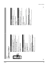
This set-up will enable you to:
–
watch or record a channel through the cable
box via the LINE IN 1 (AUDIO/VIDEO) jacks.
You will need to:
•
press
INPUT SELECT
so that the VCR display
shows
“L1
”.
Cable box
Incoming cable
Cable box
OUT
IN
Summary of Contents for W603C
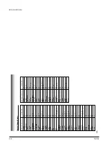
Page 20: ...Reference Information Toshiba 2 13 2 2 1 IC301 LA71072M 2 2 IC Blocks ...
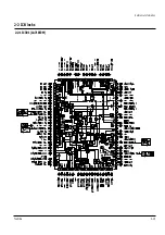
Page 21: ...Reference Information 2 14 Toshiba 2 2 2 IC501 AN3662 ...
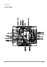
Page 22: ...Reference Information Toshiba 2 15 2 2 3 IC601 MN101D02X ...
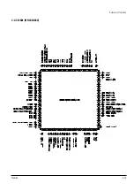
Page 23: ...Reference Information 2 16 Toshiba MEMO ...
Page 25: ...Product Specifications 3 2 Toshiba MEMO ...
Page 56: ...Alignment and Adjustment Toshiba 5 11 Fig 5 21 Main PCB Top View VR501 Location for VR501 ...
Page 57: ...5 12 Toshiba Alignment and Adjustment MEMO ...
Page 59: ...Exploded View 6 2 Toshiba 6 1 Packing Assembly A702 A701 A702 Y101 Y102 UT01 ...
Page 63: ...Exploded View 6 6 Toshiba MEMO ...
Page 73: ...Replacement Parts List 7 10 Toshiba MEMO ...
Page 74: ...Toshiba 8 1 8 Block Diagram ...
Page 75: ...Block Diagram 8 2 Toshiba MEMO ...
Page 76: ...Toshiba 9 1 9 PCB Diagrams 9 2 9 3 9 3 9 3 9 1 Main 9 2 VFD 9 3 Jack 9 4 Key ...
Page 77: ...PCB Diagrams 9 2 Toshiba 9 1 Main ...
Page 78: ...PCB Diagrams Toshiba 9 3 9 2 VFD 9 3 Jack 9 4 Key ...
Page 79: ...PCB Diagrams 9 4 Toshiba MEMO ...
Page 82: ...Schematic Diagrams Toshiba 10 3 10 1 S M P S Power ...
Page 83: ...Schematic Diagrams 10 4 Toshiba IC601 VFD 10 2 Logic ...
Page 85: ...Schematic Diagrams 10 6 Toshiba 10 3 A V ...
Page 87: ...Schematic Diagrams 10 8 Toshiba 10 4 Hi Fi MTS ...
Page 89: ...Schematic Diagrams 10 10 Toshiba 10 5 TM Block Input Ouput ...
Page 90: ...Schematic Diagrams Toshiba 10 11 10 6 VFD ...
Page 91: ...Schematic Diagrams 10 12 Toshiba 10 7 Remote Control ...


