background image


E6582175 


F-127 

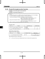
6.34  Operation panel parameter 


6.34.1 Prohibition of key operations and parameter settings 


f700

 : Parameter protection selection 


f730

 : Panel frequency setting prohibition (

fc


f731

 : Disconnection detection of extension panel 


f732

 : Local/remote key prohibition of extension panel 


f733

 : Panel operation prohibition (RUN key)


f734

 : Panel emergency stop operation prohibition


f735

 : Panel reset operation prohibition 


f736

 : 

cmod

/

fmod

 change prohibition during operation 


f737

 : All key operation prohibition 


f738

 : Password setting (

f700


f739

 : Password verification 


  Function  

These parameters allow you to prohibit or allow operation of the RUN and STOP keys on the 
operation panel and the change of parameters. Using these parameters, you can also prohibit 
various key operations. Lock parameters with a password to prevent configuration. 


[Parameter setting] 

Title 

Function 

Adjustment range 

Default setting 

f700


Parameter protection selection 
 Note1,3) 

0: Permitted 
1: Writing prohibited (Panel and 

extension panel) 

2: Writing prohibited (1 + RS485 

communication) 

3: Reading prohibited (Panel and 

extension panel) 

4: Reading prohibited (3 + RS485 

communication) 

f730

Panel frequency setting prohibition 
(

fc

0: Permitted, 1: Prohibited 




Disconnection detection of extension 
panel 

0: Permitted, 1: Prohibited 

f732

Local/remote key prohibition of 
extension panel 

0: Permitted, 1: Prohibited 

f733

Panel operation prohibition 
(RUN key) 

0: Permitted, 1: Prohibited 

Summary of Contents for TOSVERT VF-S15 series

Page 1: ...nd data Specifications Before making a service call Inspection and maintenance Warranty Disposal of the inverter NOTICE 1 Make sure that this instruction manual is delivered to the end user of the inverter unit 2 Read this manual before installing or operating the inverter unit and store it in a safe place for reference Instruction Manual Detailed manual 3 phase 240V class 0 4 to 15kW 1 phase 240V...

Page 2: ... to injury 1 to people or that these errors will cause damage to physical property 2 1 Such things as injury burns or shock that will not require hospitalization or long periods of outpatient treatment 2 Physical property damage refers to wide ranging damage to assets and materials Meanings of symbols Marking Meaning of marking Indicates prohibition Don t do it What is prohibited will be described...

Page 3: ... phase output and cannot drive a single phase motor Handling Warning Reference section Disassembly prohibited Never disassemble modify or repair This can result in electric shock fire and injury Contact your Toshiba distributor for repairs 2 Prohibited Never remove the terminal block cover when power is on The unit contains many high voltage parts and contact with them will result in electric shoc...

Page 4: ...er the environmental conditions prescribed in the instruction manual Operations under any other conditions can result in malfunction Mount the inverter on a metal plate The rear panel gets very hot Do not install in an inflammable object this can result in fire Do not operate with the terminal block cover removed This can result in electric shock Failure to do so can lead to risk of electric shock...

Page 5: ...se unexpected result as VIA terminal is ON status 2 2 2 2 2 2 2 2 Mandatory action Electrical construction work must be done by a qualified expert Connection of input power by someone who does not have that expert knowledge can result in fire or electric shock Connect output terminals motor side correctly If the phase sequence is incorrect the motor will operate in reverse and that can result in i...

Page 6: ...en the motor unexpectedly restarts 1 3 2 3 3 3 Mandatory action Turn the input power on only after attaching the terminal block cover When enclosed inside a cabinet and used with the terminal block cover removed always close the cabinet doors first and then turn the power on If the power is turned on with the terminal block cover or cabinet doors open can result in electric shock Make sure that op...

Page 7: ...l f731 If these are not properly set the inverter can not be stopped immediately in breaking communication and this could result in injury and accidents An emergency stop device and the interlock that fit with system specifications must be installed If these are not properly installed the inverter can not be stopped immediately and this could result in injury and accidents 6 38 1 6 38 1 When seque...

Page 8: ...ases resulting in injury Persons who specialize in the processing of waste and known as industrial waste product collectors and transporters or industrial waste disposal persons Please observe any applicable law regulation rule or ordinance for industrial waste disposal 16 Attach caution labels Shown here are examples of caution labels to prevent in advance accidents in relation to inverters motor...

Page 9: ...seful in searching for a parameter or changing a parameter setting D 7 4 4 Checking the region settings selection D 13 4 5 EASY key function D 14 5 Main parameters E 1 5 1 Meter setting and adjustment E 1 5 2 Setting acceleration deceleration time E 4 5 3 Maximum frequency E 5 5 4 Upper limit and lower limit frequencies E 6 5 5 Base frequency E 7 5 6 Setting the electronic thermal E 8 5 7 Preset s...

Page 10: ...78 6 23 Acceleration deceleration suspend function Dwell function F 79 6 24 PID control F 81 6 25 Setting motor constants F 88 6 26 Torque limit F 94 6 27 Acceleration deceleration time 2 and 3 F 99 6 28 Shock monitoring function F 103 6 29 Protection functions F 104 6 30 Forced fire speed control function F 118 6 31 Override F 119 6 32 Analog input terminal function selection F 122 6 33 Adjustmen...

Page 11: ... 5 11 4 Default settings by inverter rating K 33 11 5 Default settings by setup menu K 34 11 6 Input Terminal Function K 35 11 7 Output Terminal Function K 40 11 8 Application easy setting K 44 11 9 Unchangeable parameters in running K 45 12 Specifications L 1 12 1 Models and their standard specifications L 1 12 2 Outside dimensions and mass L 4 13 Before contacting your Toshiba distributor Trip i...

Page 12: ...E6582175 iv 15 Warranty O 1 16 Disposal of the inverter P 1 17 Appendix Q 1 UL standard and CSA standard Q 1 한국 KC 마크 R 1 Motor control parameter default setting update information S 1 ...

Page 13: ...ing used If the inverter being used does not conform to those specifications not only will the three phase induction motor not rotate correctly but it can also cause serious accidents through overheating and fire Inverter Type Inverter rated output capacity Power supply Rated input current Rated output current Model Power supply Motor capacity Inverter main unit Carton box Name plate Danger label ...

Page 14: ...oved WARNUNG Risk of injury electric shock or fire Read the instruction manual Ensure proper earth connection Do not open the cover while power is applied or for 15 minutes after power has been removed AVVERTENZA Risk of injury electric shock or fire Read the instruction manual Ensure proper earth connection Do not open the cover while power is applied or for 15 minutes after power has been remove...

Page 15: ...rcuit wiring Bottom view Side view Charge lamp Indicates there is a high voltage still in the inverter Do not open the terminal block cover when this lamp is lit because it is dangerous Cover This is the body and terminal block cover Always close this cover before operation to avoid accidentally touching the terminal block The serial number is recorded on the back side Door lock Slide the door loc...

Page 16: ...LED on the operation panel uses the following symbols to indicate parameters and operations LED display numbers 0 1 2 3 4 5 6 7 8 9 0 1 2 3 4 5 6 7 8 9 LED display letters Aa Bb C c Dd Ee Ff Gg H h I i Jj Kk Ll a b c w d e f g h k i j l Mm Nn O o Pp Qq Rr Ss Tt Uu Vv Ww Xx Yy Zz m n o x p q r s t u v y Insert a small screw driver and slide the door lock to upside for unlock Slide it to downside fo...

Page 17: ...er During the terminal block operation pressing this key twice for emergency stop During trip pressing this key twice for reset STOP key PRG lamp When lit the inverter is in parameter setting mode When blinking the inverter is in auh Lit when a frequency is not output with the ON run command This lamp blinks when operation starts RUN lamp lamp Displayed numbers are in Center of the setting dial Pr...

Page 18: ... to replace the terminal cover Use the following procedure to open the terminal cover and pull the power terminal block Inverter type Procedure Reference number VFS15 2004PM W1 to 2007PM W1 VFS15S 2002PL W1 to 2007PL W1 In the beginning remove the outside terminal block cover 1 Next remove the inside terminal block cover 2 VFS15 2015PM W1 to 2037PM W1 VFS15S 2015PL W1 2022PL W1 VFS15 4004PL W1 to ...

Page 19: ...ter wiring is complete be sure to restore the terminal cover to its original position 1 2 3 4 Insert a screwdriver or other thin object into the hole indicated with the mark Press in on the screwdriver While pressing on the screwdriver rotate the terminal cover downward to remove it Pull the terminal cover up at an angle ...

Page 20: ...2PL W1 to 2007PL W1 After wiring is complete be sure to restore the terminal cover to its original position 1 2 3 The finger is put on to the tab part of the terminal block cover While pressing on the screwdriver rotate the terminal cover downward to remove it Pull the terminal cover up at an angle ...

Page 21: ...1 VFS15 4004PL W1 to 4037PL W1 After wiring is complete be sure to restore the terminal cover to its original position 1 2 3 Insert a screwdriver or other thin object into the hole indicated with the mark Press in on the screwdriver While pressing on the screwdriver sidles the terminal cover downward to remove it ...

Page 22: ...g the inside terminal block cover VFS15 2015PM W1 to 2037PM W1 VFS15S 2015PL W1 2022PL W1 VFS15 4004PL W1 to 4015PL W1 After wiring is complete be sure to restore the terminal cover to its original position 1 2 3 The finger is put on to the tab part of the terminal block cover While pressing on the screwdriver rotate the terminal cover downward to remove it Pull the terminal cover up at an angle ...

Page 23: ...TA TUS PRG MON STOP Hz 5 Removing the inside terminal block cover VFS15 4022PL W1 4037PL W1 After wiring is complete be sure to restore the terminal cover to its original position 1 2 3 The finger is put on to the tab part of the terminal block cover While pressing on the screwdriver rotate the terminal cover downward to remove it Pull the terminal cover up at an angle ...

Page 24: ...to its original position 1 2 3 Insert a screwdriver or other thin object into the hole indicated with the mark Press in on the screwdriver While pressing on the screwdriver slide the terminal cover downward to remove it EASY RFS S1 S2 MODE RUN RUN STATU S PRG MON STOP Hz EASY RFS S1 S2 MODE RUN RUN STATU S PRG MON STOP Hz EASY RFS S1 S2 MODE RUN RUN STATU S PRG MON STOP Hz ...

Page 25: ...1 for details about terminal functions Screw Size Crimp style terminal Note1 Tightening torque M3 5 xxx 3 5 1 0 N m 8 9 lb in M4 xxx 4 1 4 N m 12 4 lb in M5 xxx 5 2 4 N m 20 8 lb in M6 xxx 6 4 5 N m 40 0 lb in M4 grounding terminal xxx 4 1 4 N m 12 4 lb in M5 grounding terminal xxx 5 2 8 N m 24 8 lb in Note1 xxx means wire sizes For the wire sizes refer to the table in section 10 1 VFS15 2004PM W1...

Page 26: ...w Grounding terminal M5 screw M4 screw Shorting bar For EMC plate Grounding terminal M5 screw VFS15 2015PM W1 2022PM W1 VFS15 2037PM W1 Note1 Bend the clips on the wiring port of the terminal cover to connect the PB PO PA and PC terminals Note2 Be careful to insert all wires into the cage of terminal block ...

Page 27: ...crew Shorting bar Grounding capacitor switch For EMC plate Grounding terminal M5 screw Grounding terminal M4 screw Grounding terminal M4 screw VFS15S 2002PL W1 to 2007PL W1 VFS15S 2015PL W1 2022PL W1 Note1 Bend the clips on the wiring port of the terminal cover to connect the PB PO PA and PC terminals Note2 Be careful to insert all wires into the cage of terminal block ...

Page 28: ...crew Shorting bar For EMC plate Grounding capacitor switch Grounding terminal M5 screw VFS15 4004PL W1 to 4015PL W1 VFS15 4022PL W1 4037PL W1 Note1 Bend the clips on the wiring port of the terminal cover to connect the PB PO PA and PC terminals Note2 Be careful to insert all wires into the cage of terminal block ...

Page 29: ...M5 screw Shorting bar M6 screw For EMC plate Grounding terminal M5 screw Grounding terminal M5 screw VFS15 2055PM W1 2075PM W1 VFS15 4055PL W1 4075PL W1 VFS15 2110PM W1 2150PM W1 Note1 Bend the clips on the wiring port of the terminal cover to connect the PB PO PA and PC terminals Note2 Be careful to insert all wires into the cage of terminal block ...

Page 30: ...late M5 screw Grounding terminal M5 screw Grounding terminal M5 screw VFS15 4110PL W1 4150PL W1 Note1 Bend the clips on the wiring port of the terminal cover to connect the PB PO PA and PC terminals Note2 Be careful to insert all wires into the cage of terminal block ...

Page 31: ...ree phase 500V 4 0kW model if you disconnect the capacitor from ground set the parameter of carrier frequency f300 to 4kHz or less with motor cable length 30m or less Note2 Don t disconnect the grounding capacitor with the switch if you set the overload characteristic selection aulto 2 Pressing this switches the grounding capacitor s capacity from small to large Default setting Pulling this switch...

Page 32: ...d 0 34 22 AI 0 34 6TQ DN00306 0 5 20 AI 0 5 6WH DN00506 0 75 18 AI 0 75 6GY DN00706 1 18 AI 1 6RD DN01006 1 5 16 AI 1 5 8BK DN01508 2 X 0 5 AI TWIN2 X 0 5 8WH DTE00508 2 X0 75 AI TWIN2 X 0 75 8GY DTE00708 1 Crimping pliers CRIMPFOX ZA3 PHOENIX CONTACT CT1 Dinkle International Ltd 2 These ferrules enable practical crimping of two wires in a ferrule RS485 connector Stripping length 6 mm Screwdriver ...

Page 33: ... If this happens operate with the output decreased from rated load To carry out low speed operation continuously at the rated torque we recommend to use a inverter rated motor or a forced cooled motor designed for use with an inverter When operating in conjunction with an inverter rated motor you must change the inverter s motor overload protection level to VF motor use Adjusting the overload prot...

Page 34: ... high backlash When using the inverter in the above combination use the S pattern acceleration deceleration function or when vector control is selected adjust the load inertia moment ratio or switch to V f control mode Combined with loads that have sharp fluctuations in rotation such as piston movements In this case adjust the load inertia moment ratio during vector control or switch to V f contro...

Page 35: ...ct us before designing your system Measures to protect motors against surge voltages In a system in which a 500V class inverter is used to control the operation of a motor very high surge voltages may be produced When applied to the motor coils repeatedly for a long time may cause deterioration of their insulation depending on the cable length cable routing and types of cables used Here are some e...

Page 36: ...ple will raise the output peak current making it easier to set off the overcurrent trip Power factor correction capacitor Power factor correction capacitors cannot be installed on the output side of the inverter When a motor is run that has a power factor correction capacitor attached to it remove the capacitors This can cause inverter malfunction and capacitor destruction Remove the power factor ...

Page 37: ...l a circuit interrupting fuse behind MCCB2 to MCCBn 1 If power supply distortion is not negligible If the power supply distortion is not negligible because the inverter shares a power distribution line with other systems causing distorted waves such as systems with thyristors or large capacity inverters install an input AC reactor to improve the input power factor to reduce higher harmonics or to ...

Page 38: ...eakage current may flow not just through the inverter system but also through ground wires to other systems Leakage current will cause earth leakage breakers leakage current relays ground relays fire alarms and sensors to operate improperly and it will cause superimposed noise on the TV screen or display of incorrect current detection with the CT Refer to Inverter Application Manual Leakage curren...

Page 39: ...tion 5 6 The setting of the electronic thermal is done using parameter 2 Reduce f300 PWM carrier frequency However the motor magnetic noise is increased Refer to section 6 18 3 This can be improved by installing 0 1μ to 0 5μF 1000V film capacitor to the input output terminals of each phase in the thermal relay 2 CT and ammeter If a CT and ammeter are connected externally to detect inverter output ...

Page 40: ...ng and fire Make the cable length between the inverter and the motor 100 m or less and shorten as much as possible When connecting two or more sets of motors the cable length is the total cable length The charging current of the electrostatic capacitance between cables increases as the cable length becomes long Especially for low capacity 4 0kW or less models an over current trip can become easy t...

Page 41: ...voltage is 10 15 of the rated power voltage 10 when the load is 100 in continuous operation written on the name plate If the input power voltage is not 10 15 of the rated power voltage 10 when the load is 100 in continuous operation this can result in fire Caution Prohibited Do not install the inverter in any location subject to large amounts of vibration This could cause the unit to fall resultin...

Page 42: ...easurement position Measurement position 5cm Position for measuring ambient temperature Note The inverter is a heat emitting body Make sure proper space and ventilation is provided when installing in the cabinet Do not install in any location that is subject to large amounts of vibration Note If the inverter is installed in a location that is subject to vibration anti vibration measures are requir...

Page 43: ...is necessary to hold motor shaft install a mechanical brake The brake on the inverter will not function as a mechanical hold and if used for that purpose injury will result 1 Normal installation Select an indoor location with good ventilation and then install it upright on a flat metal plate When installing multiple inverters leave at least 3 cm of space between each inverter and install them alig...

Page 44: ... 4kHz 12kHz Three phase 240V class VFS15 2004PM W1 2007PM W1 2015PM W1 2022PM W1 2037PM W1 2055PM W1 2075PM W1 2110PM W1 2150PM W1 35 40 0 20 0 23 0 70 0 80 14 45 6 50 0 26 0 28 0 91 0 99 14 81 92 0 46 0 52 1 61 1 85 16 94 9 104 0 54 0 59 1 90 2 07 16 139 154 0 79 0 87 2 77 3 08 18 256 283 1 45 1 61 5 12 5 66 22 305 367 1 73 2 08 6 10 7 34 22 475 538 2 70 3 05 9 50 10 76 31 557 628 3 16 3 56 11 14...

Page 45: ...ace them in the same conduit do not run them parallel and do not bundle them Provide shielding and twisted wire for control circuit wiring Separate the input power and output motor wires of the main circuit Do not place them in the same conduit do not run them parallel and do not bundle them Ground the inverter grounding terminals Install surge suppressor on any magnetic contactor and relay coils ...

Page 46: ...erters side by side remove the protective label on the top of the inverter When using the inverter in locations with temperatures above 40 C use the inverter with the output current reduced Ensure a space of at least 20 centimeters on the top and bottom of the inverters Install an air deflecting plate so that the heat rising up from the inverter on the bottom does not affect the inverter on the to...

Page 47: ...ower on only after attaching the terminal block cover If the power is turned on without the terminal block cover attached this can result in electric shock or other injury Electrical construction work must be done by a qualified expert Connection of input power by someone who does not have that expert knowledge can result in fire or electric shock Connect output terminals motor side correctly If t...

Page 48: ...nction or the trip use the trip holding retention selection parameter In addition please use an optional control power supply backup unit when only control power supply operates even if the main circuit is shut off due to trouble or tripping Wiring Cover the crimp style terminal with insulation tube or use the crimp style terminal with insulation sleeve when crimp style terminals are used for the ...

Page 49: ...ower side Touching the terminals and wires before that time could result in electric shock Do not shut down the external power supply on ahead when VIA terminal is used as logic input terminal by external power supply It could cause unexpected result as VIA terminal is ON status Mandatory action Set a parameter f109 when VIA or VIB terminals are used as logic input terminal If it is not set it cou...

Page 50: ...ignal output Noise filter Power circuit Motor U T1 V T2 W T3 M Current signal 4 0 20mA Voltage signal 0 10V or 10 10V 3 4 4 STO SU Frequency meter ammeter Ry 1 The T L3 terminal is not provided for single phase models Use the R L1 and S L2 N terminals as input terminals 2 The inverter is supplied with the PO and the PA terminals shorted by means of a shorting bar Before installing the DC reactor D...

Page 51: ...r U T1 V T2 W T3 M Current signal 4 0 20mA Voltage signal 0 10V or 10 10V 3 4 4 STO SU Frequency meter ammeter Ry 1 The T L3 terminal is not provided for single phase models Use the R L1 and S L2 N terminals as input terminals 2 The inverter is supplied with the PO and the PA terminals shorted by means of a shorting bar Before installing the DC reactor DCL remove the bar 3 When using the NO output...

Page 52: ... 240V class Three phase 200 to 240V 50 60Hz Single phase 200 to 240V 50 60Hz 500V class Three phase 380 to 500V 50 60Hz Single phase inputs are R L1 and S L2 N terminals U T1 V T2 W T3 Connect to three phase motor PA PB Connect to braking resistors Change parameters if necessary PA This is a positive potential terminal in the internal DC main circuit DC common power can be input between PA termina...

Page 53: ...e 10pps 2kpps Duty 50 10 PTC input S3 terminal 24V F R RES S1 S2 EXT SW1 SINK SOURCE VIB SW2 S3 4 75k 1k S3 S4 5V 4 75k 22k S3 27 4k SW2 5V PTC R Input Shorting across R CC or P24 R causes reverse rotation open causes deceleration stop When Standby ST is always ON 3 different functions can be assigned RES Input This inverter protective function is reset if RES CC or P24 RES is connected Shorting R...

Page 54: ...s terminal can also be used as a multifunction programmable logic input terminal 10Vdc internal impedance 30k 5V 15k 15k VIA 1k V I B Note 1 Input Multifunction programmable analog input Default setting 0 10Vdc 1 1000 resolution and 0 60Hz 0 50Hz frequency input The function can be changed to 10 10V input by parameter 1 setting By switching slide switch SW2 and changing parameter f109 setting this...

Page 55: ...r operating the control circuit Connect a control power backup device option or 24Vdc power supply between SU and CC Voltage 24Vdc 10 Current 1A or more Output It is used with STO for safety function SU and STO terminals are short circuited by metal bar and the inverter is put into a standby state at default setting When the circuit between them is opened the motor is coasting stop STO Note 2 Inpu...

Page 56: ...city 250Vac 2A 30Vdc 2A cos 1 at resistive load 250Vac 1A cos 0 4 30Vdc 1A L R 7ms Min permissible load 5Vdc 100mA 24Vdc 5mA RY RC Note 3 Output Multifunction programmable relay contact output Default settings detect and output low speed signal output frequencies Multifunction output terminals to which two different functions can be assigned Note 1 When VIA terminal is used as logic input terminal...

Page 57: ...nverter s internal power supply or an external power supply and its connections vary depending on the power supply used Sink source logic can be switched by slide switch SW1 Examples of connections when the inverter s internal power supply is used CC NO Source Positive logic Inverter P24 F Programmable controller Common Common Output Input Input 24VDC Output Sink Negative logic F CC Common Output ...

Page 58: ...en VIA terminal is used as logic input terminal by external power supply in SINK logic connection It could cause unexpected result as VIA terminal is ON status Sink Negative logic Slide switch SW1 PLC side Source Positive logic Slide switch SW1 PLC side 24VDC Input Input 24VDC 24VDC Output Output Inverter Programmable controller SW1 PLC side Common Common F P24 OUT NO F Output Input 24VDC Output O...

Page 59: ... using VIB terminal as an analog input terminal set the slide switch to VIB side and set the parameter When using VIB terminal as a logic input terminal set the slide switch to S4 side and set the parameter any value to or Sink source logic depends on the slide switch SW1 Match the setting of upper slide switch SW2 and parameter surely If it is not this can result in malfunction 3 Switching of S3 ...

Page 60: ...ys turn the power off if the inverter is not used for long periods of time since there is a possibility of malfunction caused by leaks dust and other material If power is left on with the inverter in that state it can result in fire Turn the input power on only after attaching the terminal block cover When enclosed inside a cabinet and used with the terminal block cover removed always close the ca...

Page 61: ...ge of the motor connected See the table on the following page Follow these steps to change the setup menu Example Selecting a region code to eu Panel operated LED display Operation set set is blinking Turn the setting dial and select region code eu Europe eu in it Press the center of the setting dial to determine the region 0 0 The operation frequency is displayed Standby If you want to change the...

Page 62: ...ency voltage 1 2 240V class 230 V 230 V 230 V 200 V 500V class 400 V 460 V 400 V 400 V pt V F control mode selection 0 0 0 2 f307 Supply voltage correction output voltage limitation 2 2 2 3 f319 Regenerative over excitation upper limit 120 120 120 140 f417 Motor rated speed Refer to section 11 4 Note 1 Excludes Japan Note 2 Slide switch SW1 is set to PLC side at default setting Set it appropriatel...

Page 63: ... Function Adjustment range Default setting cmod Command mode selection 0 Terminal block 1 Panel keypad including extension panel 2 RS485 communication 3 CANopen communication 4 Communication option 1 fmod Frequency setting mode selection 1 0 Setting dial 1 save even if power is off 1 Terminal VIA 2 Terminal VIB 3 Setting dial 2 press in center to save 4 RS485 communication 5 UP DOWN from external ...

Page 64: ...he parameter set value are displayed alternately 1 Run and stop using the panel keypad cmod 1 Use the and keys on the panel keypad to start and stop the motor Motor runs Motor stops The direction of rotation is determined by the setting of parameter forward run reverse run selection forward run reverse run Forward run and reverse run are switchable with the extension panel option Set the parameter...

Page 65: ...op Inverter will display off at Coast stop 1 Assign 6 ST to an input terminal Set parameter Open the ST CC for coast stop see the status described on the right 2 Assign 96 FRR to an input terminal Coast stop is done by shorting FRR and CC Motor speed ON OFF ON OFF F CC ST CC Coast stop ...

Page 66: ...l option fmod 0 or 3 Moves the frequency up Moves the frequency down For an extension panel option key moves the frequency up key moves the frequency down Example of operating from the panel press in center to save Panel operation LED display Operation Displays the output frequency When standard monitor display selection output frequency Set the frequency command value The frequency will not be sa...

Page 67: ...lt setting Title Function Setting value Command mode selection 1 Frequency setting mode selection 1 0 3 Operation Run stop Press the and keys on the panel Frequency setting Turn the setting dial to set the frequency The frequency setting is saved just by turning the setting dial 1 Single phase models are R L1 and S L2 N Ex 1 Motor M R L1 S L2 T L3 U T1 V T2 W T3 Operation panel MCCB PB PA PO PC 1 ...

Page 68: ... and keys on the panel Frequency setting Turn the setting dial to set the frequency To save the frequency setting press the center of the setting dial and the set frequency will flash on and off alternately then set frequency will be retained The set frequency will be retained even if power supply is cut 1 Single phase models are R L1 and S L2 N Ex 2 Motor M R L1 S L2 T L3 U T1 V T2 W T3 Operation...

Page 69: ...de selection 1 0 or 3 3 Operation Run stop ON OFF input to F CC R CC with sink logic F is for forward run signal and R is for reverse run signal default setting Frequency setting Turn the setting dial to set the frequency 1 Single phase models are R L1 and S L2 N Ex 3 Motor M F R L1 S L2 T L3 U T1 V T2 W T3 Forward signal R CC Reverse signal Common MCCB Operation panel PB PA PO PC 1 ...

Page 70: ... Frequency setting VIA Input 0 10V external potentiometer VIB Input 0 10V or 10 10Vdc or VIC 4 0 20mA to set the frequency Set the selection of VIA VIB or VIC in parameter VIA VIB VIC Refer to section 7 3 for the setting of analog input characteristics 1 Single phase models are R L1 and S L2 N Ex 4 Motor M F R L1 S L2 T L3 U T1 V T2 W T3 Forward signal R Reverse signal MCCB CC VIC Common Current s...

Page 71: ...d Parameters can be registered as necessary max 32 parameters Standard setting mode Both basic and extended all parameters are displayed Each press of the EASY key switches between the Easy setting mode and the Standard setting mode This mode is for monitoring the output frequency and setting the frequency reference value If also displays information about status alarms during running and trips Di...

Page 72: ...tion Refer to chapter 8 The inverter can be moved through each of the modes by pressing the MODE key y Setting monitor mode Status monitor mode Standard monitor mode At power source on MODE MODE MODE RUN MON PRG PRG Frequency setting method Refer to section 3 2 2 How to search and set parameters Refer to section 4 2 Monitoring of operation status Refer to section 8 2 ...

Page 73: ...tor electronic thermal protection level 1 fm Meter adjustment gain f701 Current voltage unit selection psel EASY key mode selection If the EASY key is pressed while the setting dial is being turned values continue to be incremented or decremented even if you release your finger from the setting dial This feature is handy when setting large values Note Of the available parameters number value param...

Page 74: ...his parameter is a basic parameter for the operation of the inverter Refer to chapter 5 for details Refer to section 11 2 for parameter tables Extended parameters The parameters for detailed and special setting Refer to chapter 6 for details Refer to section 11 3 for parameter tables Note There are the parameters that cannot be changed during inverter running for reasons of safety Refer to section...

Page 75: ...monitor mode std is displayed and the mode is switched Standard monitor mode 1 3 2 4 Parameter title and the setting value are displayed alternately Registered parameters Max 32 parameters MODE MODE Basic parameter setting Easy setting mode Registered parameters at default setting Title Function cmod Command mode selection fmod Frequency setting mode selection 1 acc Acceleration time 1 dec Deceler...

Page 76: ...e setting dial To switch to the Easy setting mode press the EASY key in the Standard monitor mode easy is displayed and the mode is switched When you are unsure of something during operation You can return to the Standard monitor mode by pressing the MODE key several times y Standard parameters MODE MODE MODE MODE Standard monitor mode Parameter title and the setting value are displayed alternatel...

Page 77: ...story function auh This function automatically searches for the last five parameters whose settings have been changed To use this function select the auh parameter The changed parameters are displayed regardless of difference with the default settings The parameters set by communication option or RS485 communication are not searched and not displayed Refer to section 6 1 1 for details Easy setting...

Page 78: ...es for only those parameters that are programmed with values different from the default setting To use this function select the gru parameter Refer to section 4 3 1 for details 4 3 1 Searching for and resetting changed parameters gru Automatic edit function Note 1 If you reset a parameter to its factory default the parameter will no longer appear in gru Note 2 It may take several seconds to displa...

Page 79: ...meter in the reverse direction 8 0 Press the center of the setting dial to display set values 5 0 Turn the setting dial and change set values 5 0 acc Press the center of the setting dial to set values The parameter name and set value light alternately and are written u f u r Use the same steps as those above and turn the setting dial to display parameters to search for or whose settings must be ch...

Page 80: ...lete initialization 0 This function will be displayed as 0 during reading on the right This previous setting is displayed on the left Example 3 0 typ cannot be set during the inverter operating Always stop the inverter first and then program Programmed value 50 Hz default setting typ 1 Setting typ to 1 sets the following parameters for base frequency 50 Hz use The setting values of other parameter...

Page 81: ...ata is cleared Trip record clear typ 4 Setting typ to 4 initializes the past eight sets of recorded error history data The parameter does not change Cumulative operation time clear typ 5 Setting typ to 5 resets the cumulative operation time to the initial value zero Initialization of type information typ 6 Setting typ to 6 clears the trips when an etyp format error occurs But if the displayed cont...

Page 82: ...ion time to the initial value zero Set this parameter when replacing the cooling fan and so on Number of starting clear typ 12 Setting typ to12 resets the number of starting to the initial value zero Default setting 2 typ 13 Set typ to 13 to return all parameters to their default settings When 13 is set init is displayed for a short time after the settings are configured and then disappears Then s...

Page 83: ...ion settings The number displayed when parameter set is read indicates which of the following regions was selected on the setup menu 4 eu Europe is selected on the setup menu 3 asia Asia Oceania is selected on the setup menu 2 usa North America is selected on the setup menu 1 jp Japan is selected on the setup menu The setup menu is started by setting set 0 Refer to section 3 1 for details Note 1 t...

Page 84: ...re read out and displayed varies according to the mode selected Easy setting mode Allows pre registration easy setting mode parameters of frequently changed parameters and reading of only registered parameters maximum of 32 types In the Easy setting mode the EASY key lamp lights Standard setting mode Standard setting mode in which all parameters are read out How to read out parameters Use the EASY...

Page 85: ...sy setting mode Press the EASY key to switch to standard mode psel 2 Always in easy setting mode However it can be switched to standard setting mode by EASY key if it is set to psel 0 1 When psel is not displayed in Easy setting mode undo is displayed and it can be temporarily switched to standard setting mode by EASY key after center of the setting dial is pushed for five seconds or more ...

Page 86: ...2999 6 fm f759 Easy setting mode parameter 9 0 2999 Set by communication number 999 No function f760 Easy setting mode parameter 10 f761 Easy setting mode parameter 11 f762 Easy setting mode parameter 12 f763 Easy setting mode parameter 13 f764 Easy setting mode parameter 14 f765 Easy setting mode parameter 15 f766 Easy setting mode parameter 16 f767 Easy setting mode parameter 17 f768 Easy settin...

Page 87: ...95 is set to 1 Enabled it can be switched during operation Local means panel operation Remote means the operation that is selected by command mode selection cmod and frequency setting mode selection fmod f207 In the Local mode the EASY key lamp lights Note Please note that if set the parameter f750 to 0 in local mode the panel operation state holds and it becomes different from setting of cmod Pea...

Page 88: ...ue 8 9 Motor cumulative load factor 10 Inverter cumulative load factor 11 PBR Braking resistor cumulative load factor 12 Stator frequency 13 VIA input value 14 VIB input value 15 Fixed output 1 output current 100 equivalent 16 Fixed output 2 output current 50 equivalent 17 Fixed output 3 Other than the output current 18 RS485 communication data 19 For adjustments set value is displayed 20 VIC inpu...

Page 89: ...e setting dial to adjust the meter The meter s indicator will change by turning setting dial The inverter displays output frequency and it will not change with the setting dial Press the center of the setting dial to save the meter s adjustments and the frequency are displayed alternately The display returns to displaying output frequency When standard monitor display selection is set to output fr...

Page 90: ... that inverter rated current output current 100 equivalent passes will be output from the FM terminal Adjust the meter with the Meter adjustment parameter in this state Similarly if you set to for fixed output 2 output current 50 equivalent a signal assuming that 50 of inverter rated current output current 50 equivalent passes will be output from the FM terminal After meter adjustment is ended set...

Page 91: ...ting of acceleration deceleration time unit 0 1 0 01s unit after execution 0 2 0 1s unit after execution 0 0 Note1 Setting increment unit can be changed to 0 01 seconds by parameter f519 Note2 f519 2 When the acceleration deceleration time is set to 0 0 seconds the inverter accelerates and decelerates 0 05 seconds f519 1 When the acceleration deceleration time is set to 0 00 seconds the inverter a...

Page 92: ...ime Output frequency Hz When 80Hz When 60Hz 80Hz 60Hz 0 100 Frequency setting signal This function determines the value in line with the ratings of the motor and load Maximum frequency cannot be adjusted during operation To adjust first stop the inverter If is increased adjust the upper limit frequency as necessary Parameter setting Title Function Adjustment range Default setting Maximum frequency...

Page 93: ...d frequency Hz Command frequency Hz Parameter setting Title Function Adjustment range Default setting Upper limit frequency 0 5 Hz 1 Lower limit frequency 0 0 Hz 0 0 1 Default setting values vary depending on the setup menu setting Refer to section 11 5 Note1 Do not set a value 10 times larger than base frequency 1 and base frequency 2 for If a large number is set the output frequency can only be ...

Page 94: ...ncy Note This is an important parameter that determines the constant torque control area Output voltage V Base frequency voltage Output frequency Hz 0 Parameter setting Title Function Adjustment range Default setting Base frequency 1 20 0 500 0 Hz 1 Base frequency voltage1 50 330 240V class 50 660 500V class 1 1 Default setting values vary depending on the setup menu setting Refer to section 11 5 ...

Page 95: ...or Parameter setting Title Function Adjustment range Default setting Overload characteristic selection 0 4 1 Constant torque characteristic 150 60s 2 Variable torque characteristic 120 60s 0 Motor electronic thermal protection level 1 10 100 A 1 100 Electronic thermal protection characteristic selection Setting value Overload protection Overload stall 0 0 Standard motor valid invalid 1 valid valid...

Page 96: ...hermal protection characteristics selection is used to enable or disable the motor overload trip function ol2 and the overload stall function The inverter overload trip ol1 can be selected with using the parameter f631 The main module overload trip ol3 is detected constantly by the temperature estimation Explanation of terms Overload stall This is an optimum function for equipment such as fans pum...

Page 97: ... start level is fixed at 30Hz Example of setting When the VFS15 2007PM W1 is running with a 0 4kW motor having 2A rated current Operation panel action LED display Operation Displays the output frequency Perform during operation stopped When standard monitor display selection is set to 0 output frequency The first basic parameter history function is displayed Turn the setting dial to change the par...

Page 98: ...quals the inverter s rated output current A 1 0 Output frequency Hz Output current reduction factor A 0 Note The start level for motor overload reduction is fixed at 6 Hz 6Hz 0 6 2 Motor 150 overload detection time f607 Parameter f607 is used to set the time elapsed before the motor trips under a load of 150 overload trip 2 within a range of 10 to 2400 seconds 3 Inverter overload detection method ...

Page 99: ...his parameter adjusts automatically overload protection predicting the inverter internal temperature rise diagonally shaded area in the figure below Inverter overload protection characteristics 60 100 Inverter rated output current time s Inverter overload Monitored output current 0 110 150 Current Inverter overload time s Outline data 111 2400 120 242 130 120 140 80 150 60 175 3 200 0 5 f631 0 60 ...

Page 100: ... to characteristic for aul 2 setting refer to section 5 6 5 4 Electronic thermal memory f632 When the power is OFF it is possible to reset or maintain the overload totaling level This parameter s settings are applied both to the motor s electronic thermal memory and the electronic thermal memory for inverter protection Parameters settings Title Function Adjustment range Default setting f632 Electr...

Page 101: ...setting be sure to install the input AC reactor ACL between power supply and inverter to remove the protective label on the top of the inverter and to connect the grounding capacitors by pressing the grounding capacitor switch Then to use the inverter at 40 C or less of the ambient temperature with setting f300 to 4 0 kHz or less aul 2 Variable torque characteristic f631 0 120 60s Inverter overloa...

Page 102: ...nitor Overload and region setting of section 8 2 1 6 Overload alarm level f657 When the motor overload level reaches to f657 setting value of overload trip ol2 level l will be displayed on the left side digit and the l and output frequency monitor will be blinking alternately on overload alarm status Overload alarm signal can be output from output terminal Parameters settings Title Function Adjust...

Page 103: ...et speed frequency setting a Set the speed frequency of the number of steps necessary Parameter setting Preset speed 0 Title Function Adjustment range Default setting sr0 Preset speed frequency 0 Hz 0 0 fmod Frequency setting mode selection 1 0 13 14 sr0 0 Frequency command set with sr0 is valid when fmod 14 sr0 sr0 is valid even when the command mode selection is not cmod 0 Setting from speed 1 t...

Page 104: ...ds are valid when all are OFF Terminal Preset speed 1 2 3 4 5 6 7 8 9 10 11 12 13 14 15 S1 CC S2 CC S3 CC RES CC Terminal functions are as follows Terminal S1 Input terminal function selection 4A S1 10 Preset speed command 1 SS1 Terminal S2 Input terminal function selection 5 S2 12 Preset speed command 2 SS2 Terminal S3 Input terminal function selection 6 S3 14 Preset speed command 3 SS3 Terminal ...

Page 105: ...14 sr0 0 Setting dial 1 save even if power is off 1 Terminal VIA 2 Terminal VIB 3 Setting dial 2 press in center to save 4 RS485 communication 5 UP DOWN from external logic input 6 CANopen communication 7 Communication option 8 Terminal VIC 9 10 11 Pulse train input 12 13 14 sr0 Preset speed command Active Preset speed command valid Note Inactive Command set with fmod is valid Note The preset spee...

Page 106: ...12 13 14 sro 0 f207 Frequency setting mode selection 2 1 f200 Frequency priority selection 0 fmod Switchable to f207 by terminal input 1 fmod Switchable to f207 at 1 0 Hz or less of designated frequency 0 Note When setting the frequency by an extension panel option fmod f207 is set to 0 or 3 1 Switching with input terminal signals Input terminal function 104 105 FCHG Frequency priority selection p...

Page 107: ...on parameter f200 1 Switch frequency command set with fmod and f207 automatically according to the frequency command entered If the frequency set with fmod is above 1Hz The frequency command set with fmod If the frequency set with fmod is 1Hz or less The frequency command set with f207 ...

Page 108: ...after power has been restored restarts the motor smoothly motor speed search function This parameter also allows switching from commercial power operation to inverter operation without stopping the motor During operation rtry is displayed Parameter setting Title Function Adjustment range Default setting f301 Auto restart control selection 0 Disabled 1 At auto restart after momentary stop 2 At ST t...

Page 109: ...restart it takes about 1 second for the inverter to check the number of revolutions of the motor For this reason the start up takes more time than usual Use this function when operating a system with one motor connected to one inverter This function may not operate properly in a system configuration when multiple motors are connected to one inverter In case of using this function do not set the ou...

Page 110: ... in amperes volts Parameter setting Title Function Adjustment range Default setting f701 Current voltage unit selection 0 1 A ampere V volt 0 The f701 converts the following parameter settings A display Current monitor display Load current torque current Motor electronic thermal protection level 1 2 f173 DC braking current f251 Stall prevention level 1 2 f601 f185 Small current detection current f...

Page 111: ...e display mode from 60Hz default setting to 1800min 1 the rotating speed of the 4P motor Hz 2 Displaying the speed of the loading unit To switch the display mode from 60Hz default setting to 6m min 1 the speed of the conveyer Note This parameter displays the inverter output frequency as the value obtained by multiplying it by a positive number This does not mean that the actual motor speed or line...

Page 112: ...01 f102 f167 f190 f192 f194 f196 f198 f202 f204 f211 f213 f217 f219 f240 f241 f242 f250 f260 f265 f267 f268 f270 to f275 f287 f294 f330 f331 f346 f350 f367 f368 f383 f390 to f393 f505 f513 f649 f812 f814 a923 to a927 In case of f703 1 Free unit PID control related parameters fpid f367 f368 Note The unit of the Base frequency 1 and 2 are always Hz An example of setting when fh is 80 and f702 is 10 ...

Page 113: ... Preset speed frequency 0 7 5 7 fpid Set value of PID control 6 24 typ Default setting 4 3 2 set Checking the region setting 4 4 psel EASY key mode selection 4 5 gru Automatic edit function 4 3 1 f200 Frequency priority selection 5 8 f207 Frequency setting mode selection 2 f287 f294 Preset speed frequency 8 15 5 7 f301 Auto restart control selection 5 9 f519 Setting of acceleration deceleration ti...

Page 114: ...Press the center of the setting dial to display the set value 5 0 Turn the setting dial to change the set value 5 0 acc Press the center of the setting dial to save the changed value The parameter name and the programmed value will flash on and off alternately Turn the dial as described above to search for and display changed parameters to check and change the settings head end head First historic...

Page 115: ...f700 Parameter protection selection f737 All key operation prohibition f738 Password setting f700 f739 Password verification 6 1 2 Application easy setting aua aua Application easy setting Parameter setting Title Function Adjustment range Default setting aua Application easy setting 0 1 Initial easy setting 2 Conveyor 3 Material handling 4 Hoisting 5 Fan 6 Pump 7 Compressor 0 Application easy sett...

Page 116: ...ting dial to the right to change the parameter to aua 0 Set values are displayed by pressing the center of the setting dial 2 Turn the setting dial to the right to select 1 or 2 2 aua Press the center of the setting dial to save the changed set value aua and the set value are displayed alternately 2 The parameters necessary to the machine are set to easy setting mode parameter 1 32 Refer to the ch...

Page 117: ...f216 f762 sr2 sr2 f308 f202 f202 f217 f763 sr3 sr3 f309 f203 f203 f218 f764 sr4 sr4 f328 f204 f204 f219 f765 sr5 sr5 f329 f207 f207 fpid f766 sr6 sr6 f330 f216 f216 f359 f767 sr7 sr7 f331 f217 f217 f360 f768 f201 f240 f332 f218 f218 f361 f769 f202 f243 f333 f219 f219 f362 f770 f203 f250 f334 f295 f295 f363 f771 f204 f251 f340 f301 f301 f366 f772 f240 f252 f341 f302 f302 f367 f773 f243 f304 f345 f3...

Page 118: ...he settings Guidance function auf The guidance function refers to the special function of calling up only functions necessary to set up the inverter in response to the user s needs When a purpose specific guidance is selected a group of parameters needed for the specified application function is formed and the inverter is switched automatically to the mode of setting the group of parameters select...

Page 119: ...ess the center of the setting dial to display the purpose specific guidance parameter group refer to following table After moving to the purpose specific guidance parameter group use the setting dial to change the parameters is displayed on completion of the setting of the guidance parameter group Display of parameter Press the MODE key to exit the guidance parameter group Thereafter return to the...

Page 120: ...ion Function This automatically adjusts acceleration and deceleration time in line with load Refer to section 5 2 for setting acceleration deceleration time manually Adjusts the acceleration deceleration time automatically within the range of 1 8 to 8 times as long as the time set with the or depending on the current rating of the inverter Automatically adjusts speed during acceleration only Durin...

Page 121: ... Do not set when using a dynamic braking resistor optional Methods of setting automatic acceleration deceleration Operation panel action LED display Operation Displays the output frequency When standard monitor display selection is set to output frequency The first basic parameter history function is displayed Turn the setting dial to the right to change the parameter to Set values are displayed b...

Page 122: ...at the start of the motor 1 Increasing torque automatically according to the load is set to Automatic torque boost auto tuning When torque boost setting macro function control is set to 1 automatic torque boost auto tuning the inverter keeps track of the load current in any speed range and automatically adjusts the output voltage to ensure enough torque and stable operation Note 1 The same charact...

Page 123: ... to energy saving auto tuning the inverter always passes a current appropriate to the load for energy saving Note 5 The same characteristic can be obtained by setting the V F control mode selection parameter to automatic energy saving and the auto tuning parameter to auto tuning Refer to section 6 25 Note 6 Setting to automatically programs to Example of parameter setting Operation panel action LE...

Page 124: ...oost auto tuning Automatic torque boost control Auto tuning executed after execution 0 Vector control auto tuning Vector control Auto tuning executed after execution 0 Energy saving auto tuning Energy saving Auto tuning executed after execution 0 4 Increasing torque manually V F constant control This is the setting of constant torque characteristics that are suited for such things as conveyors It ...

Page 125: ...of an external signal run and stop operation Panel keypad operation Press the and keys on the panel keypad to run and stop Operation can also be done from the extension panel RS485 communication Run stop operations by RS485 communication from an external device Refer to section 6 38 3 CANopen communication Run stop operations by CANopen communication from an external device Refer to CANopen commun...

Page 126: ... set by keys on an extension panel option Refer to section 3 2 2 Terminal VIA A frequency command is set by means of external analog signals VIA terminal 0 10Vdc Refer to section 3 2 2 and 7 3 Terminal VIB A frequency command is set by means of external analog signals VIB terminal 0 10Vdc or 10 10Vdc Refer to section 3 2 2 and 7 3 Setting dial 2 Frequencies are set by rotating the setting dial on ...

Page 127: ...ndby External input tripping stop command Coast stop command terminal To make changes in the command mode selection and the frequency setting mode selection 1 first stop the inverter temporarily Can be changed while in operation when is set to Priority commands from communications or terminal blocks are given priority over Preset speed operation Set to Terminal block operation Valid in all setting...

Page 128: ...quency setting mode selection 1 RS485 communications Terminal block active FMTB Input terminal function 106 107 Panel keypad Terminal block active CMTB Input terminal function 108 109 RS485 communication priority clear SCLC Input terminal function 48 49 With extension panel option RKP007Z Frequency setting mode forced switching FCHG 104 105 Terminal VIB CANopen communication Communication option T...

Page 129: ...ension panel RKP002Z option When is set to and the standard monitor is displayed pressing the DOWN key while pressing the ENT key changes the direction of rotation from forward to reverse after displaying the message Pressing the UP key while pressing the ENT key again changes the direction of rotation from reverse to forward after displaying the message Check the direction of rotation on the stat...

Page 130: ...section 6 1 5 Parameter setting Title Function Adjustment range Default setting V F control mode selection 0 V F constant 1 Variable torque 2 Automatic torque boost control 3 Vector control 4 Energy saving 5 Dynamic energy saving For fan and pump 6 PM motor control 7 V F 5 point setting 8 3 2 2 Default setting values vary depending on the setup menu setting Refer to section 11 5 3 8 is manufacture...

Page 131: ... F control mode selection Set values are displayed by pressing the center of the setting dial Rotate the setting dial to the right and change the parameter to vector control Press the center of the setting dial to save the changed set value and the set value are displayed alternately Caution When the V F control mode selection is set to Automatic torque boost control Vector control Energy saving D...

Page 132: ...t frequency Hz Base frequency 0 To increase the torque further increase the setting value of the manual torque boost value 1 Refer to section 6 4 for details 2 Setting for fans and pumps Setting of V F control mode selection to variable torque This is appropriate for load characteristics of such things as fans pumps and blowers in which the torque is proportional to the square of load rotation spe...

Page 133: ...us setting of auto torque boost and auto tuning f400 2 Set the basic parameter Torque boost setting macro function to Refer to section 6 1 5 for details 2 Automatic setting Set the extended parameter auto tuning to Refer to section 6 25 selection 2 for details 3 Manual setting Set each motor constant Refer to section 6 25 selection 4 for details 4 Vector control increasing starting torque and achi...

Page 134: ... section 6 1 5 for details 2 Automatic setting Set the extended parameter auto tuning to Refer to section 6 25 selection 2 for details 3 Manual setting Set each motor constant Refer to section 6 25 selection 4 for details 6 Achieving further energy savings Setting of V F control mode selection to Dynamic energy saving More substantial energy savings than those provided by setting to can be achieve...

Page 135: ...te the motor while switching a maximum of 5 different V f characteristics Parameter setting Title Function Adjustment range Default setting V f 5 point setting VF1 frequency Hz V f 5 point setting VF1 voltage V V f 5 point setting VF2 frequency Hz V f 5 point setting VF2 voltage V V f 5 point setting VF3 frequency Hz V f 5 point setting VF3 voltage V V f 5 point setting VF4 frequency Hz V f 5 poin...

Page 136: ...w The minimum applicable motor capacity is 0 1kW 5 Use a motor that has 2 8 P 6 Always operate the motor in combination of one motor for one inverter Sensorless vector control cannot be used when one inverter is operated with more than one motor When using a combination of several motors set the V F constant 7 The maximum length of wires between the inverter and motor is 30 meters If the wires are...

Page 137: ...ltage Output frequency Hz Base frequency Parameter setting Title Function Adjustment range Default setting Torque boost value 1 0 0 30 0 According to model Refer to section 11 4 Valid when is set to 0 V F constant 1 Variable torque or 7 V F 5 point setting Note 1 The optimum value is programmed for each inverter capacity by default setting Be careful not to increase the torque boost rate too much ...

Page 138: ...al RY RC Default Output from the terminal FLA FLB FLC and OUT are possible by the parameter settings Parameter setting Title Function Adjustment range Default setting f100 Low speed signal output frequency 0 0 fh Hz 0 0 Output frequency Time s Low speed detection signal OUT NO terminals ON OFF Inversion of low speed detection signal ON OFF Hz 0 Setting frequency Output terminal setting Low speed s...

Page 139: ...tion band 0 0 fh Hz 2 5 Parameter setting of output terminal selection Title Function Adjustment range Default setting f131 Output terminal selection 2A OUT 0 255 Refer to section 11 7 6 RCH Output frequency attainment signal acceleration deceleration completed Setting value 7 is reverse signal Note Set f132 to output to FLA FLC FLB terminals and f130 to RY RC terminal Output frequency Hz Time s D...

Page 140: ...requency 0 0 fh Hz 0 0 f102 Speed reach detection band 0 0 fh Hz 2 5 Parameter setting of output terminal selection Title Function Adjustment range Setting f131 Output terminal selection 2A OUT 0 255 Refer to section 11 7 8 RCHF Set frequency attainment signal Setting value 9 is reverse signal Note Set f132 to assign to FLA FLC FLB terminals and f130 to RY RC terminal If the detection band value t...

Page 141: ...mmand are entered simultaneously 1 Reverse 2 Deceleration stop Parameter setting Title Function Adjustment range Default setting f105 Priority selection Both F and R are ON 0 Reverse 1 Deceleration stop 1 1 f105 0 Reverse If an F command and an R command are entered simultaneously the motor will run in the reverse direction Output frequency Hz Forward run Reverse run Forward run command Reverse ru...

Page 142: ...ltage range of VIB terminal f107 Analog input terminal selection VIB Function This parameter allows you to choose the voltage signal input for the VIB terminal Parameter setting Title Function Adjustment range Default setting f107 Analog input terminal selection VIB 0 0 10V 1 10 10V 0 f107 0 Input 0 to 10Vdc to VIB CC terminals Resolution is maximum 1 1000 between 0 to 10Vdc f107 1 Input 10 to 10V...

Page 143: ...0 VIA analog input VIB analog input 0 1 VIA analog input VIB contact input 2 3 VIA contact input Sink VIB contact input 4 VIA contact input Source VIB contact input Note When using VIA terminal as contact input terminals be sure to insert a resistor between P24 terminal and VIA terminal in sink logic connection and insert a resistor between VIA terminal and CC terminal in source logic connection R...

Page 144: ...ve function selection 1 0 7 10 153 Refer to section 11 6 8 9 0 No function f108 Always active function selection 2 0 7 10 153 Refer to section 11 6 8 9 0 No function f110 Always active function selection 3 0 7 10 153 Refer to section 11 6 8 9 6 ST Explanation of the coast stop function When ST Standby is OFF coast stops The default setting for ST Standby is ON Please change the following settings ...

Page 145: ...ut terminal selection 3B RES f154 Input terminal selection 4B S1 f155 Input terminal selection 1C F f156 Input terminal selection 2C R f144 Input terminal response time f146 Logic input pulse input selection S2 f147 Logic input PTC input selection S3 Refer to section 7 2 1 for details about input terminal functions 6 7 3 Modifying output terminal functions f130 Output terminal selection 1A RY RC f...

Page 146: ...eter is enabled only for motor 1 If motor 2 is selected V F control will be given constant torque characteristics Parameter setting Title Function Adjustment range Default setting f170 Base frequency 2 20 0 500 0 1 f171 Base frequency voltage 2 50 330 V 240V class 50 660 V 500V class 1 f172 Torque boost value 2 0 0 30 0 Depending on model Refer to section 11 4 f173 Motor electronic thermal protect...

Page 147: ...OFF OFF During stop pt V F constant vl f170 vlv f171 vb f172 thr f173 During run vl f170 vlv f171 vb f172 OFF OFF OFF ON OFF f601 f185 OFF ON is fixed when or Note 1 Each of the following numbers 25 27 29 33 153 are reverse signals Note 2 pt and V F constant cannot be switched while running Stop the motor before switching When the motor is switched wait for starting to drive for 0 2 seconds or mor...

Page 148: ...VF3 voltage f196 V f 5 point setting VF4 frequency f197 V f 5 point setting VF4 voltage f198 V f 5 point setting VF5 frequency f199 V f 5 point setting VF5 voltage For details refer to 8 of section 6 3 6 10 Frequency priority selection 6 10 1 Using two frequency commands according to the particular situation fmod Frequency setting mode selection 1 f200 Frequency priority selection f207 Frequency s...

Page 149: ...t 2 setting f219 VIC input point 2 frequency f810 Communication command point selection f811 Communication command point 1 setting f812 Communication command point 1 frequency f813 Communication command point 2 setting f814 Communication command point 2 frequency Function Output frequency is adjusted in relation to frequency command according to external analog signals VIA and VIB terminals are se...

Page 150: ...ng 100 100 0 f211 VIB input point 1 frequency 0 0 500 0 Hz 0 0 f212 VIB input point 2 setting 100 100 100 f213 VIB input point 2 frequency 0 0 500 0 Hz 1 f216 VIC input point 1 setting 0 100 0 f217 VIC input point 1 frequency 0 0 500 0 Hz 0 f218 VIC input point 2 setting 0 100 100 f219 VIC input point 2 frequency 0 0 500 0 Hz 1 f810 Communication command point selection 0 Disabled 1 Enabled 0 f811...

Page 151: ... current input adjustment VIC terminal Adju st t he fr eq ue nc y c om m and f or th e cu rr en t in pu t b y s ettin g the t wo po ints S et to in cas e o f a cu rr e nt in pu t o f 0 to 2 0 m A 10 0 2 0mA cu rre n t sig nal 0 Hz 2 0 4mA 50 60 Hz Frequency commnd 3 10 10 Vdc voltage input adjustment VIB terminal Adjust the frequency command for the voltage input by setting the two points 50 60 Hz...

Page 152: ...4 f210 to f213 f216 to f219 The figure below shows the characteristic of the frequency command input through the VI terminal and that of the output frequency Bias adjustment of analog input terminal f470 f472 f474 Decrease the value in case frequency is output even though the frequency command is 0 zero Hz Gain adjustment of analog input terminal f471 f473 f475 Increase the value in case the outpu...

Page 153: ...ernal logic input DOWN response time 0 0 10 0 s 0 1 f267 External logic input DOWN frequency steps 0 0 fh Hz 0 1 f268 Initial value of UP DOWN frequency Hz 0 0 f269 Change of the initial value of UP DOWN frequency 0 Not changed 1 Setting of changed when power is turned off 1 This function is valid when the parameter fmod Frequency setting mode selection 1 5 is set Input terminal settings Assigning...

Page 154: ...c f265 f264 setting time fh dec f267 f266 setting time Sample sequence diagram 1 Adjustment with continuous signals The dotted line denotes the output frequency obtained by combining the slowdown speed and the panel frequency adjustment speed Frequency 0 Hz Lower limit frequency Gradient f267 f266 Gradient f265 f264 Upper limit frequency DOWN signal UP signal Forward reverse command Set frequency ...

Page 155: ... of initial up down frequency to 0 Not changed The change of the initial up down frequency To make the inverter automatically save the frequency immediately before the power is off and start operation at that frequency next time power is on set f269 change of initial up down frequency to 1 which changes the setting of f268 when power is turned off Keep in mind that the setting of f268 is changed e...

Page 156: ...79 Pulse train input filter 2 1000 ms 2 This function is valid when the parameter fmod 11 Pulse train input and f146 1 Pulse train input are set Number of pulses per 1Hz of output frequency is set by parameter f378 Example of setting f378 25 pps Input signal 25 pps Output frequency 1 0 Hz Input signal 100 pps Output frequency 4 0 Hz Input signal 2k pps Output frequency 80 0 Hz f378 50 pps Input si...

Page 157: ... frequency below the rated slippage of the motor When starting Frequency set with f240 is output instantly When stopping Output frequency turns to be 0Hz instantly with the frequency set with f243 Parameter setting Title Function Adjustment range Default setting f240 Starting frequency 0 1 10 0 Hz 0 5 f243 Stop frequency setting 0 0 Same as f240 0 1 30 0 Hz 0 0 Note Set these parameters so that th...

Page 158: ...frequency command Parameter setting Title Function Adjustment range Default setting f241 Operation starting frequency 0 0 fh Hz 0 0 f242 Operation starting frequency hysteresis 0 0 fh Hz 0 0 0 A B 100 Frequency command value When the frequency command signal reaches the B point the inverter operates When decelerating operation stops when the frequency setting signal is less than point A Output fre...

Page 159: ...raking time 0 0 25 5 s 1 0 Time s DC braking starting frequency DC braking current DC braking time Output frequency Hz DC braking Operation signal F CC ON OFF Output current A 0 0 Set frequency Note1 During DC braking the overload protection sensitivity of the inverter increases The DC braking current may be adjusted automatically to prevent tripping Note 2 During DC braking the carrier frequency ...

Page 160: ... set to 1 half amount of the braking force set with f251 DC braking rate will make the motor continue DC braking even after the completion of ordinary DC braking To stop motor shaft fixing control turn off the standby command ST signal DC injection braking start frequency LED display Time s Output frequency Hz Operation signal F CC ON OFF Output current A 0 0 Set frequency Operation standby signal...

Page 161: ...limit frequency operation Function If operation at the lower limit frequency is carried out for the time set with the inverter will automatically decelerate the motor to stop for the purpose of energy saving At that time is displayed alternately on the operation panel Stop by this function will be canceled if a frequency command value exceeds the lower limit frequency ll f391 Hz or if the operatio...

Page 162: ...signal immediately generates a jog run frequency output irrespective of the designated acceleration time Also you can choose the jog run start stop mode from the panel Assign 18 jog run mode to an input terminal Ex When assigning it to the RES terminal f113 to 18 The motor can be operated in jog mode while the assigned input terminals are connected RES CC ON Parameter setting Title Function Adjust...

Page 163: ...un RES JOG ON R ON Reverse jog run Frequency command F ON Forward run Frequency command R ON Reverse run The jog run setting terminal RES CC is enabled when the value of operation frequency is that of the jog run frequency and below This connection does not function when operation frequency exceeds the jog run frequency The motor can be operated in jog mode while the jog run setting terminals are ...

Page 164: ...ng as the key is pressed When rjog is displayed the inverter will be placed in reverse jog run mode as long as the key is pressed If you press and hold down the key for 20 seconds or more the key failure alarm e 17 will be displayed Here is the sequence in which modes change each time you press the key Standard monitor mode Statusmonitor mode Setting monitor mode Panel jog mode M ODE MODE MODE M O...

Page 165: ...or Jumping width 1 Jumping width 2 Jumping width 3 Jump frequency 3 Jump frequency 1 Jump frequency 2 Output command frequency Hz Frequency setting signal 0 Parameter setting Title Function Adjustment range Default setting f270 Jump frequency 1 0 0 fh Hz 0 0 f271 Jumping width 1 0 0 30 0 Hz 0 0 f272 Jump frequency 2 0 0 fh Hz 0 0 f273 Jumping width 2 0 0 30 0 Hz 0 0 f274 Jump frequency 3 0 0 fh Hz...

Page 166: ...on 0 Disabled 1 Enabled 0 f732 Local remote key prohibition of extension panel 0 Permitted 1 Prohibited 1 EASY key function selection 0 Easy standard setting mode switching function 1 Shortcut key 2 Local remote key 3 Monitor peak minimum hold trigger 4 5 0 Set Local remote function to key f750 EASY key function selection 2 Local remote key EASY lamp is lighting during local mode Local mode is the...

Page 167: ...s are moved to Local mode when switching from Remote mode to Local mode Motor runs continuously for the case described on the left When switching from Local mode to Remote mode setting frequency and start stop status are determined by Remote mode status For the case described on the left the motor runs continuously because the Remote mode is run status To prevent from moving the setting frequency ...

Page 168: ...with machinery etc 1 When reducing the magnetic noise of the motor increase f300 PWM carrier frequency If f300 cannot be increased set f312 random mode to random mode to reduce magnetic noise of the motor 2 When reducing the noise from the inverter decrease f300 However the magnetic noise of the motor is increased 3 When reducing the resonance with the machinery or the fan cover of the motor chang...

Page 169: ...ent reduction may be required Refer to the table on the following page Note 2 PWM carrier frequency is increased automatically at high output frequency range 100 Hz or more for stable operation even if f300 is set to low PWM carrier frequency Note 3 When f300 is set to 8kHz or less the random mode is exercised in the low output frequency range where an annoying magnetic noise of the motor is gener...

Page 170: ... 2 A 2015PM L W1 40 C or less 8 0 A 7 9 A 7 1 A Above 40 50 C 8 0 A 7 9 A 7 1 A Above 50 60 C 7 6 A 6 3 A 5 7 A 2022PM L W1 40 C or less 11 0 A 10 0 A 9 1 A Above 40 50 C 11 0 A 10 0 A 9 1 A Above 50 60 C 10 5 A 8 0 A 7 3 A 2037PM W1 40 C or less 17 5 A 16 4 A 14 6 A Above 40 50 C 17 5 A 16 4 A 14 6 A Above 50 60 C 16 6 A 13 1 A 11 7 A 2055PM W1 40 C or less 27 5 A 25 0 A 25 0 A Above 40 50 C 27 5...

Page 171: ...e 50 60 C 3 9 A 3 0 A 2 6 A 4022PL W1 40 C or less 5 5 A 5 0 A 4 5 A Above 40 50 C 5 5 A 5 0 A 4 5 A Above 50 60 C 5 2 A 4 0 A 3 6 A 4037PL W1 40 C or less 9 5 A 8 6 A 7 5 A Above 40 50 C 9 5 A 8 6 A 7 5 A Above 50 60 C 9 0 A 6 9 A 6 0 A 4055PL W1 40 C or less 14 3 A 13 0 A 13 0 A Above 40 50 C 14 3 A 13 0 A 13 0 A Above 50 60 C 13 6 A 10 4 A 10 4 A 4075PL W1 40 C or less 17 0 A 17 0 A 14 8 A Abov...

Page 172: ...A 4055PL W1 40 C or less 13 2 A 12 0 A 12 0 A Above 40 50 C 13 2 A 12 0 A 12 0 A Above 50 60 C 12 5 A 9 6 A 9 6 A 4075PL W1 40 C or less 15 6 A 14 2 A 12 4 A Above 40 50 C 15 6 A 14 2 A 12 4 A Above 50 60 C 14 8 A 11 4 A 9 9 A 4110PL W1 40 C or less 25 5 A 23 0 A 23 0 A Above 40 50 C 25 5 A 23 0 A 23 0 A Above 50 60 C 24 2 A 18 4 A 18 4 A 4150PL W1 40 C or less 30 4 A 27 6 A 24 0 A Above 40 50 C 3...

Page 173: ...1 40 C or less 9 6 A 2022PM W1 40 C or less 12 0 A 2037PM W1 40 C or less 19 6 A 2055PM W1 40 C or less 30 0 A 2075PM W1 40 C or less 38 6 A 2110PM W1 40 C or less 56 0 A 2150PM W1 40 C or less 69 0 A VFS15S Ambient temperature PWM carrier frequency 2 0k 4 0kHz 2002PL W1 40 C or less 1 9 A 2004PL W1 40 C or less 4 1 A 2007PL W1 40 C or less 5 5 A 2015PL W1 40 C or less 10 0 A 2022PL W1 40 C or les...

Page 174: ...nverter to remove the protective label on the top of the inverter and to connect the grounding capacitors by pressing the grounding capacitor switch Then to use the inverter at 40 C or less of the ambient temperature with setting f300 to 4 0 kHz or less If parameter f316 0 2 or 4 and current is increased to main module overheat level ol3 or to overheat level oh the l alarm or h alarm occurs If the...

Page 175: ...tor 2 Deceleration stop during power failure When momentary power failure occurs during operation this function stops the motor quickly and compulsorily using the regeneration energy from the motor Deceleration time varies according to the load When the function of the deceleration stop during power failure operates the message is displayed on the operation panel After the forced stop the inverter...

Page 176: ...7 and that of f318 respectively Note 2 Even if these functions are used a motor may coast according to load conditions In this case use the auto restart function f301 for the smooth restart after power supply is restored Note 3 Jog run function doesn t operate at synchronized acceleration deceleration An example of setting when f302 1 When power is interrupted The time for which the operation of t...

Page 177: ...ltage in main circuit falls below main circuit under voltage moff level at the deceleration stop operation during power failure the motor will coast and inverter displays stop and 0 0 alternately The motor continues coasting even after power supply is restored Time Input voltage Deceleration stop Motor speed Motor speed Note 5 If momentary power failure occurs during deceleration stop power ride t...

Page 178: ...ration function increases the output frequency to the frequency at the start of synchronized deceleration or to the command frequency whichever is lower to accelerate the motor linearly within the time specified with f318 The S pattern operation function the braking sequence or the auto tuning function cannot be used along with this function When acceleration is started the message stop disappears...

Page 179: ...E6582175 F 67 6 Motor speed Time Inverter 1 Inverter 2 ON Input voltage 1 Power failure synchronized signal terminal S1 ON OFF ...

Page 180: ...by an unusual event other than overcurrent overvoltage overload overheating or step out This function will also be canceled if retrying is not successful within the specified number of times Retry is done only when the following trips occur oc1 oc2 oc3 op1 op2 op3 ol1 ol2 ol3 oh sout Protective operation detection relay signals FLA FLB FLC terminal signals are not sent during use of the retry func...

Page 181: ...h as a press Parameter setting Title Function Adjustment range Default setting f304 Dynamic braking selection 0 Disabled 1 Enabled Resistor overload protection enabled 2 Enabled 3 Enabled Resistor overload protection enabled At ST terminal on 4 Enabled At ST terminal on 0 f308 Dynamic braking resistance 1 0 1000 Depending on models See Section 11 4 f309 Dynamic braking resistor capacity 0 01 30 00...

Page 182: ...reventing overload and overcurrent to protect the braking resistor the thermal relay is activated in case the protection function fails to work Select and connect a thermal relay THR appropriately to the capacity wattage of the braking resistor Connecting thermal relays and an external braking resistor IM Motor R L1 S L2 T L3 U T1 V T2 W T3 Main circuits Power supply PA PB MCCB Braking resistor op...

Page 183: ... a lift a press or a tension control machine or in applications that require deceleration stopping of a machine with a significant load inertial moment increase the dynamic braking resistor capacity according to the operation rate required To connect an external dynamic braking resistor select one with a resultant resistance value greater than the minimum allowable resistance value Be sure to set ...

Page 184: ...g are optionally available For more information contact your Toshiba distributor Note 3 Type form of PBR indicates the thermal fuse Type form of PBR7 indicates the thermal fuse and thermal relay Note 4 The default setting values of parameter f308 Dynamic braking resistance and f309 Dynamic braking resistor capacity are applied to braking resistor option 3 Minimum resistances of connectable braking...

Page 185: ...etup menu setting Refer to section 11 5 2 100 corresponds to an input voltage of 200V for 240V models or to an input voltage of 400V for 500V models If f305 is set to 2 quick deceleration control the inverter will increase the voltage to the motor over excitation control to increase the amount of energy consumed by the motor when the voltage reaches the overvoltage protection level during decelera...

Page 186: ...50 330 240V class 50 660 500V class 1 f307 Supply voltage correction output voltage limitation 0 Supply voltage uncorrected output voltage limited 1 1 Supply voltage corrected output voltage limited 2 Supply voltage uncorrected output voltage unlimited 3 Supply voltage corrected output voltage unlimited 1 Default setting values vary depending on the setup menu setting Refer to section 11 5 If f307...

Page 187: ...oltage V Input voltage Output frequency vl High Low 0 Input voltage vlv Input voltage High Low Output voltage V Output frequency 0 Note that the output voltage exceeding vlv is produced at the output frequency of vl base frequency or more even if vlv base frequency voltage 1 is set to the input voltage or less Input voltage High Low Output voltage V Output frequency 0 Input voltage High Low Output...

Page 188: ...l f320 Droop gain f323 Droop insensitive torque band f324 Droop output filter Function Drooping control has the function to prevent loads from concentrating at a specific motor because of a load imbalance when multiple inverters are used to operate one machine These parameters are used to allow the motor to slip according to the load torque current The insensitive torque band and the gain can be a...

Page 189: ...quency during power running During regenerative braking control is performed to increase the frequency The drooping control function is activated above the torque current set with f323 The amount of droop frequency Δf varies depending on the amount of torque current T1 Note If the base frequency vl exceeds 100Hz count it as 100Hz Control is exercised between the starting frequency f240 and the max...

Page 190: ... power running f336 Heavy load torque during power running f337 Heavy load torque during constant power running f338 Switching load torque during regenerative braking Refer to Functions for lift application E6581871 for details 6 22 Braking function 6 22 1 Brake sequence control f325 Brake releasing waiting time f326 Brake releasing small current detection level f340 Creeping time 1 f341 Braking m...

Page 191: ...53 Deceleration suspend time 0 0 10 0 s 0 0 Note1 The acceleration suspend frequency f350 should not be set below the starting frequency f240 Note2 The deceleration suspend frequency f352 should not be set below the stop frequency f243 Note3 If the output frequency is lowered by a stall prevention function the acceleration suspend function may be activated Function This function suspends accelerat...

Page 192: ...constant speed Output frequency Hz Time s Acceleration deceleration suspend signal Ex When setting the acceleration deceleration suspend signal to S3 terminal Title Function Adjustment range Example of setting f116 Input terminal selection 6 S3 0 203 60 Acceleration deceleration suspend signal Function No 61 is the inversion signal Note If the operation signal is ON after Acceleration deceleration...

Page 193: ...ing time f369 PID control feedback signal selection f360 PID control f372 Process increasing rate f361 Delay filter speed type PID control f362 Proportional gain f373 Process decreasing rate speed type PID control f363 Integral gain f380 PID forward reverse characteristics selection f366 Differential gain f389 PID set value signal selection Stall control The inverter will automatically change the ...

Page 194: ...01 100 0 0 30 f363 Integral gain 0 01 100 0 0 20 f366 Differential gain 0 00 2 55 0 00 f367 Upper limit of set value 0 0 fh Hz 60 0 1 f368 Lower limit of set value 0 0 Hz 0 0 f369 PID control feedback signal selection 0 Disabled 1 Terminal VIA 2 Terminal VIB 3 Terminal VIC 4 to 6 0 f372 Process increasing rate speed type PID control 0 1 600 0 s 10 0 f373 Process decreasing rate speed type PID cont...

Page 195: ...IB 3 Terminal VIC 4 to 6 Note 1 When setting f389 do not select the same signal used for feedback value Note 2 When f389 3 is set the PID set value is set by the parameter fpid fpid can be set by the setting dial in the standard monitor mode Please inactivate the frequency setting by the setting dial fc Preset speed frequency Set fmod f207 to other than 0 or 3 f660 to other than 4 f724 to 0 Note 3...

Page 196: ... 4 Adjusting the PID control gain level Adjust the PID control gain level according to the PID set value the feedback value and the object to be controlled Parameter settings Title Function Adjustment range Default setting f362 Proportional gain P 0 01 100 0 0 30 f363 Integral gain I 0 01 100 0 1 s 1 0 20 f366 Derivative gain D 0 00 2 55 s 0 00 f362 P gain adjustment parameter This parameter adjus...

Page 197: ... ON f366 D gain adjustment parameter This parameter adjusts the differential gain level during PID control This gain increases the speed of response to a rapid change in deviation difference between the PID set value and the feedback value Note that setting the gain beyond necessity may cause fluctuations in output frequency and thus operation to become unstable Assign function number 52 PID integ...

Page 198: ...ter ignores feedback value carries out operation at the frequency determined by the frequency command value for the period of time specified with f359 and enters the PID control mode after the elapsed time 7 PID control forward reverse characteristic switch PID input characteristics can be reversed PID set value Feedback value 1 PID Output Opposite characteristic Original characteristic Characteri...

Page 199: ...the feedback value from f369 match the range of f167 an ON or OFF signal will be sent out from the output terminal Assign function number 144 145 Signal in accordance of PID set value to an output terminal PIDset value agreement signal Inverted PID set value f389 ON OFF ON OFF PID set value agreement signal ...

Page 200: ...ing f400 independently 3 Combining the V F control mode selection pt and manual tuning Caution If the settings for V F control mode selections pt are 2 automatic torque boost control 3 vector control 4 energy saving and 5 Dynamic energy saving make sure to confirm the motor s name plate and set the following parameters vl Base frequency 1 rated frequency vlv Base frequency voltage 1 rated voltage ...

Page 201: ...otor during tuning even though it barely rotates During tuning is displayed on the operation panel 3 Tuning is performed when the motor starts for the first time after f400 is set to 2 Tuning is usually completed within three seconds If it is aborted the inverter trips with the display of etn1 and no constants are set for that motor Set f400 to 0 and perform manual tuning with selection 4 4 High s...

Page 202: ... operation can be suppressed by setting a large value in this parameter Be careful as setting a value larger than necessary may lead to an increased current and then cause a trip at low speeds Perform adjustments according to the actual operation f405 Set the motor s rated capacity according to the motor s name plate or test report f415 Set the rated current of the motor For the rated current see ...

Page 203: ...ted frequency that is calculated from Back EMF vlv Base frequency voltage 1 rated voltage that is calculated from Back EMF f405 Motor rated capacity f415 Motor rated current f417 Motor rated speed f912 Q axis inductance per phase f913 D axis inductance per phase Selection 1 Setting PM motor control and auto tuning After setting pt 6 auto tuning occurs Set the auto tuning parameter f400 to 2 Auto t...

Page 204: ...ufficient circuit protection such as mechanical braking Insufficient motor torque while tuning may cause machine stalling falling 6 If auto tuning is impossible or an etn1 auto tuning error is displayed perform manual tuning with Selection 2 Selection 2 Setting PM motor control and manual tuning If an etn1 tuning error is displayed during auto tuning or when PM motor control characteristics are to...

Page 205: ...he rated rotational speed of the motor For the rated current see the motor s nameplate or test report Adjustment method for the moment of inertia of the load f459 Adjusts the excess response speed A larger value gives a smaller overshoot at the acceleration deceleration completion point In the default settings the moment of inertia of the load including the motor shaft value is optimally set consi...

Page 206: ...stant torque in the constant output zone This function will not work when the parameter 7 setting Setting methods When setting limits to torque use internal parameters Torque limits can also be set with an external control device With the parameter f454 you can select the item for limit treatment in the constant output zone somewhat weak magnetic field from constant output f454 0 default setting o...

Page 207: ...leration operation after torque limit Function Using this function in combination with the mechanical brake of the lifting gear such as a crane or hoist makes it possible to minimize the delay before the brake starts working and thus prevents the load from falling due to torque decrease Moreover it improves the motor s response during inching operation and keeps the load from sliding down Paramete...

Page 208: ...ctual speed is kept in sync with the operation frequency while torque is held at a limit level in spite of torque decrease when releasing the mechanical brake The use of this function prevents the load from failing and improves the motor s response during inching operation Frequency Hz Torque N m Torque limit level Mechanical brake Time s Actual speed Acceleration rates vary depending on the torqu...

Page 209: ... and trips Parameter setting Title Function Adjustment range Default setting f452 Power running stall continuous trip detection time 0 00 10 00 s 0 00 f441 Power running torque limit 1 level 0 249 250 Disabled 250 f601 Stall prevention level 1 10 199 200 disabled 150 1 In case of overcurrent stall ot2 trip is occurred if the output current reached the stall prevention level f601 or more and this s...

Page 210: ...ue limitation ot2 trip is occurred if the output torque reached the power running torque limit level f441 or more and this situation maintain in f452 during power running Time s Output frequency Hz Time s Output torque less than 2 trip ...

Page 211: ... 2 0 f506 S pattern lower limit adjustment amount 0 50 10 f507 S pattern upper limit adjustment amount 0 50 10 1 Linear acceleration deceleration A general acceleration deceleration pattern This pattern can usually be used 2 S pattern 1 acceleration deceleration Select this pattern to accelerate decelerate the motor rapidly to an output frequency above 60Hz or to minimize the shocks applied during...

Page 212: ...00 Acceleration time 2 f501 Deceleration time 2 f503 Acceleration deceleration 2 pattern f504 Acceleration deceleration selection 1 2 3 panel keypad f505 Acceleration deceleration 1 and 2 switching frequency f510 Acceleration time 3 f511 Deceleration time 3 f512 Acceleration deceleration 3 pattern f513 Acceleration deceleration 2 and 3 switching frequency f519 Setting of acceleration deceleration ...

Page 213: ...ing 1 Selection using parameters Time s Output frequency Hz 0 Acceleration deceleration time 1 is initially set as the default Acceleration deceleration time 2 and 3 can be selected by changing the setting of the f504 Enabled if cmod panel input enabled 2 Switching by frequencies Switching the acceleration deceleration time automatically at the setting frequency Title Function Adjustment range Def...

Page 214: ...n at the gradient corresponding to deceleration time dec 3 Switching using external terminals Switching the acceleration deceleration time via external terminals 1 Acceleration at the gradient corresponding to acceleration time acc 2 Acceleration at the gradient corresponding to acceleration time f500 3 Acceleration at the gradient corresponding to acceleration time f510 4 Deceleration at the grad...

Page 215: ...S pattern acceleration deceleration 1 3 S pattern acceleration deceleration 2 Title Function Adjustment range Setting value f502 Acceleration deceleration 1 pattern 0 Linear 1 S pattern 1 2 S pattern 2 0 f503 Acceleration deceleration 2 pattern 0 f512 Acceleration deceleration 3 pattern 0 For an explanation of acceleration deceleration patterns see 6 27 1 Both the settings of the S pattern lower l...

Page 216: ...lace Do not set the stall prevention level parameter f601 below 30 under normal use conditions Function This parameter adjusts the output frequency by activating a current stall prevention function against a current exceeding the specified level Parameter setting Title Function Adjustment range Default setting f601 Stall prevention level 1 10 199 A 200 Disabled 150 f185 Stall prevention level 2 Di...

Page 217: ...retained even if power is turned off and turned back on during retry operation Flow of operation when f602 Occurrence of a trip Reset the inverter by panel or terminal operation Turn power off then turn it back on to reset the inverter Completion of reset If the cause of the trip is not eliminated If the cause of the trip is eliminated Normal operation The relay trips again Display of the cause Fa...

Page 218: ...n to S2 terminal Title Function Adjustment range Setting f114 Input terminal selection 4A S1 0 203 20 EXT Emergency stop by external signal Setting value 21 is reverse signal Note 1 Emergency stopping via the specified terminal is possible even during panel operation 2 Emergency stop from the operation panel Emergency stop from the operation panel is possible by pressing the STOP key on the panel ...

Page 219: ... one second or more Failure signal FL activated f605 3 The inverter checks for output phase failures during operation The inverter will trip if the phase failure status persists for one second or more Failure signal FL activated f605 4 The inverter checks for output phase failures at the start and during operation The inverter will trip if the phase failure status persists for one second or more F...

Page 220: ...r If this actually happens install an AC or DC reactor f608 0 No tripping Failure signal FL not activated f608 1 Phase failure detection is enabled during operation The inverter will trip if the abnormal voltage status of main circuit capacitor persists for few minutes or more Failure signal FL activated Parameter setting Title Function Adjustment range Default setting f608 Input phase failure det...

Page 221: ...erminal f610 1 The inverter will trip if a current below the current set with f611 flows for the period of time specified with f612 Failure signal FL activated Parameter setting Title Function Adjustment range Default setting f609 Small current detection hysteresis 1 20 10 f610 Small current trip alarm selection 0 Alarm only 1 Tripping 0 f611 Small current detection current 0 150 A 0 f612 Small cu...

Page 222: ...Parameter setting Title Function Adjustment range Default setting f613 Detection of output short circuit at start up 0 Each time standard pulse 1 Only one time after power on standard pulse 2 Each time short pulse 3 Only one time after power on short pulse 0 6 29 9 Ground fault detection function f614 Ground fault detection selection Function This parameter detects inverter ground fault If a groun...

Page 223: ... put out by setting the output terminal function selection parameter f615 1 The inverter trips when a torque exceeding the f616 specified level has been detected for longer than the f618 specified time Failure signal FL activated Parameter setting Title Function Adjustment range Default setting f615 Over torque trip alarm selection 0 Alarm only 1 Tripping 0 f616 Over torque detection level 0 disab...

Page 224: ...e ambient temperature is high or during operation This function will extend the service life of the cooling fan than when it is always running while the power is ON f620 0 Cooling fan automatically controlled Cooling fan operates only when the ambient temperature is high during operation f620 1 Cooling fan not automatically controlled The fan is always running when the inverter is on If the ambien...

Page 225: ...tive operation alarm signal output function to the OUT terminal Title Function Adjustment range Setting f131 Output terminal selection 2A OUT 0 255 56 COT Cumulative operation time alarm Setting value 57 is reverse signal The cumulative operation time until present time can be checked in status monitor mode Refer to chapter 8 The monitor value of cumulative operation time is reset to 0 zero by set...

Page 226: ...ut break detection VIC f649 Fallback frequency Function The inverter will output a trip or an alarm if the VIC value remains below the specified value for about 0 3 seconds In such a case trip e 18 and alarm a 18 is displayed f633 0 Disabled Not detected f633 1 100 The inverter will output a trip or an alarm if the VIC input remains below the specified value for about 0 3 seconds Parameter setting...

Page 227: ...mation in the Status monitor mode Refer to chapter 8 An example of display Output of part replacement alarm signal The parts replacement alarm is assigned to the output terminal Setup example When the parts replacement alarm is assigned to the OUT terminal Title Function Adjustment range Setting f131 Output terminal selection 2A OUT 0 255 128 LTA Parts replacement alarm Setting value 129 is revers...

Page 228: ...g 2 Alarm only 1 f646 PTC detection resistor value 100 9999 Ω 3000 Note Protecting PTC thermal set f147 1 PTC input and slide switch SW2 to PTC side Tripping level is defined by f646 setting Alarm level is defined by 60 of f646 setting Connect the PTC between S3 and CC terminals Detection temperature can be set by f646 setting Connection Output of PTC input alarm signal The PTC input alarm is assi...

Page 229: ...onitor mode allows you to check on the time of replacement Refer to chapter 8 An example of display Output of number of starting alarm signal The number of starting alarm is assigned to the output terminal Setup example When the number of starting alarm is assigned to the OUT terminal Title Function Adjustment range Setting f131 Output terminal selection 2A OUT 0 255 162 NSA Number of starting ala...

Page 230: ...ut terminal function 58 FIRE Input signal is retained once signal is ON Motor runs at the speed set by the parameter f294 Note In either case power terminal should be off in order to stop Parameter setting Title Function Adjustment range Default setting f650 Forced fire speed control selection 0 Disabled 1 Enabled 0 f294 Preset speed frequency 15 ll ul Hz 0 0 Setup example of input terminal When t...

Page 231: ... reference frequencies by means of external input Parameter setting Title Function Adjustment range Default setting VIA input point 1 rate 0 250 0 VIA input point 2 rate 0 250 100 VIB input point 1 rate 250 250 0 VIB input point 2 rate 250 250 100 VIC input point 1 rate 0 250 0 VIC input point 2 rate 0 250 100 f660 Override addition input selection 0 Disabled 1 Terminal VIA 2 Terminal VIB 3 Termin...

Page 232: ...verride input Ex 2 VIB Reference frequency VIA Override input Ex 1 f660 3 VIC input f661 0 disabled Output frequency Reference frequency Override VIC input Hz Ex 2 f660 1 VIA input f661 0 disabled Output frequency Reference frequency Override VIA input Hz Value selected with 100 Output frequency Over ridden frequency Override VI II input 0 10V Over ridden frequency Override VIC input 0 10V VIA inp...

Page 233: ...quency 1 Override VIC input 100 Ex 2 f660 0 Disabled f661 1 VIA input fmod 2 VIB input fh 8 0 ul 8 0 VIB input f210 0 f211 0 f212 100 f213 8 0 VIA input f201 0 f205 0 f203 100 f206 100 Setting of VIB input Refer to Section 7 3 3 Setting of VIA input Refer to Section 7 3 1 Output frequency Reference frequency 1 Override VIA input 100 Ex 3 Title Function Adjustment range Default setting f729 Operati...

Page 234: ...minal function assigns VIB terminal The range of analog input voltage is 0 to 100 From 100 to 0 cannot be used The parameter that is selected by f663 can be adjusted range as following table Setting of f663 Object parameter VIB 0 input VIB 100 input 0 Frequency command 1 Acceleration deceleration time acc dec f500 f501 f510 f511 Parameter setting value f214 Parameter setting value f215 2 Upper lim...

Page 235: ...width 0 1 1 0 s 0 1 Setting example When integral input power pulse is output from output terminal Title Function Adjustment range Setting Output terminal selection 2A 0 255 180 IPU Integral input power pulse output signal There is no reverse signal 6 33 2 Pulse train output for meters f669 Logic output pulse train output selection OUT f676 Pulse train output function selection OUT f677 Maximum nu...

Page 236: ...23 PID feedback value 24 52 53 PBR Braking resistor load factor fh 185 fh 150 150 185 185 250 100 100 100 fh 10 V 10 V 185 185 100 100 0 20mA 100 100 0 f677 Maximum numbers of pulse train output 0 50 2 00 kpps 0 80 f678 Pulse train output filter 2 1000 ms 64 Digital panel meter for reference Type K3MA F OMRON Connection terminal OUT E4 NO E5 Note 1 When item of f676 reaches Reference of max value ...

Page 237: ...quency meter When using QS60T set f681 0 meter option 0 to 1mA output Parameter setting Title Function Adjustment range Default setting f681 Analog output signal selection 0 Meter option 0 to 1mA 1 Current 0 to 20mA output 2 Voltage 0 to 10V output 0 f684 Analog output filter 2 1000 ms 2 f691 Inclination characteristic of analog output 0 Negative inclination downward slope 1 Positive inclination u...

Page 238: ...1 1 f692 0 f681 1 f691 1 f692 20 Output current Output current f681 1 f691 0 f692 100 f681 1 691 0 f692 100 Output current Output current The analog output inclination can be adjusted using the parameter Refer to section 5 1 about how to adjustment ...

Page 239: ...allow operation of the RUN and STOP keys on the operation panel and the change of parameters Using these parameters you can also prohibit various key operations Lock parameters with a password to prevent configuration Parameter setting Title Function Adjustment range Default setting f700 Parameter protection selection Note1 3 0 Permitted 1 Writing prohibited Panel and extension panel 2 Writing pro...

Page 240: ...Set 1 f731 1 to prohibit the frequency setting 1 Setup and resetting method when protection using a password is necessary Password setup method Preparation Parameters other than f700 f738 and f739 cannot be changed when f700 is set to 1 to 4 1 When f738 or f739 is read out and the value is 0 a password hasn t been set You can set a password 2 When f738 or f739 is read out and the value is 9999 a p...

Page 241: ...ameter f700 can be changed at any time even if it is set to 1 2 Canceling he f737 prohibition setting When this parameter is set to 1 key operation prohibited press and hold down the key for 5 seconds or more The message und appears and this setting is canceled temporarily to enable key operation To cancel this setting permanently change the setting of f737 directly 3 Setup method when parameter p...

Page 242: ... turning the setting dial to the right frequency will not be increased beyond this point with the hi alarm when the frequency exceeds ul Upper limit frequency with just one more step rotation Similarly when decreasing the frequency by turning the setting dial to the left and if the frequency falls below ll lower limit frequency with just one more step rotation the lo alarm is displayed in advance ...

Page 243: ...60 Hz and also the value displayed on the operation panel changes in steps of 1 Use these settings to hide decimal fractions and also the value displayed on the operation panel changes in steps of 1 Use these settings to hide decimal fractions 6 34 5 Select the initial display of the panel f710 Initial panel display selection f720 Initial extension panel display selection Function This parameter s...

Page 244: ...feedback value Hz free unit 24 Integral Input power kWh 25 Integral Output power kWh 26 Motor load factor 27 Inverter load factor 28 Inverter rated current A 29 FM output value 30 Pulse train output value pps 31 Cumulative power on time 100 hours 32 Cumulative fan operation time 100 hours 33 Cumulative operation time 100 hours 34 Number of starting 10000 times 35 Forward number of starting 10000 t...

Page 245: ...e motor is at a standstill the values monitored last are held as they were until the motor is started the next time The maximum and minimum values monitored after power is turned on is always displayed no matter whether the motor is in operation or at a standstill The maximum and minimum values are cleared to press the EASY key by setting f750 to 3 Output current Input voltage Output voltage and T...

Page 246: ...restarts due to clearing coast stop at coast stop Inverter restarts due to supply power source again when the under voltage in main circuit alarm occurs Operation command cleared Inverter doesn t restart after coast stop or occurring the under voltage in main circuit alarm Press RUN key to operate again in panel operation Switch to ON the operation command in RS485 communication operation Title Fu...

Page 247: ...the motor The motor comes to a stop after coasting for a while Depending on the load the motor may keep running for a longer time Parameter setting Title Function Adjustment range Default setting f721 Panel stop pattern 0 Deceleration stop 1 Coast stop 0 6 34 10 Select the panel display at power on f790 Panel display selection at power on f791 1st and 2nd characters of f792 3rd and 4th characters ...

Page 248: ...FFF 2d2d 7th and 8th characters of 0 FFFF 2d2d Select and set displayed characters with to if it is displayed characters other than hello Refer to ASCII LED of Communication Function Instruction Manual E6581913 about setting characters and set by hex number 6 35 Tracing functions f740 Trace selection f741 Trace cycle f742 Trace data 1 f743 Trace data 2 f744 Trace data 3 f745 Trace data 4 For detai...

Page 249: ...etting f748 Integrating wattmeter retention selection 0 Disabled 1 Enabled 0 f749 Integrating wattmeter display unit selection Note 1 0 1 1kWh 1 1 10kWh 2 1 100kWh 3 1 1000kWh 4 1 10000kWh Depends on the capacity Refer to section 11 4 Note 1 The description of the adjustment range is for the conversion of the inverter monitor display Refer to the RS485 Communication Function Instruction Manual E65...

Page 250: ...ock read data 3 f811 Communication command point 1 setting f878 Block read data 4 f812 Communication command point 1 frequency f879 Block read data 5 f813 Communication command point 2 setting f899 Communication function reset Warning Mandatory action Set the parameter Communication time out time f803 Communication time out action f804 and Disconnection detection of extension panel f731 If these a...

Page 251: ...e to multiple inverters with a single communication Peer to peer communication Refers to the function that enables the master inverter to send the data selected with a parameter to all slave inverters on the same network This function allows you to set up a network that makes it possible to carry out synchronized operation or proportional operation setting of point frequencies in an abbreviated ma...

Page 252: ...top 2 Trip Deceleration stop 0 f805 Communication waiting time 0 00 2 00 0 00 f806 Setting of master and slave for communication between inverters 0 Slave 0 Hz command issued in case the master inverter fails 1 Slave Operation continued in case the master inverter fails 2 Slave Emergency stop tripping in case the master inverter fails 3 Master transmission of frequency commands 4 Master transmissi...

Page 253: ...11 Terminal VIC monitor 12 Input voltage DC detection 13 Motor speed 14 Torque 0 f876 Block read data 2 0 f877 Block read data 3 0 f878 Block read data 4 0 f879 Block read data 5 0 f899 Communication function reset 0 1 Reset after execution 0 0 1 Disabled Indicates that the inverter will not be tripped even if a communication error occurs Trip The inverter trips when a communication time over occu...

Page 254: ...s of system Wiring 2 wire Transmission distance 500 m max total length Connection terminals 32max including upper host computer Inverters connected in the system 32max Synchronization scheme Start stop synchronization Communication baud rate 9600 bps to 38 4kbps Character transmission ASCII mode JIS X0201 8 bit ASCII Binary mode Binary codes fixed to 8 bits Binary codes fixed to 8 bits Error detec...

Page 255: ...e cable 1 Data is sent from the host computer 2 Data from the computer is received at each inverter and the inverter numbers are checked 3 The command is decoded and processed only by the inverter with the selected inverter number 4 The selected inverter responds by sending the processing results together with its own inverter number to the host computer 5 As a result only the selected inverter st...

Page 256: ...d processed 4 To prevent data conflicts only inverters where is overwritten to 0 can reply with data to the host computer 5 As a result all inverters are operating with the broadcast operation frequency command Note Specify inverter numbers by group for group broadcasts Function only for ASCII mode For parity mode see the Communications Function Instruction Manual Ex When 1 is set inverters 01 11 ...

Page 257: ...rter calculate a frequency reference from the data received and save the frequency calculated 3 As a result all slave inverters operate at the same frequency as the master inverter Note The master inverter always sends frequency command data to its slave inverters The slave inverters are always on standby so that they can receive an frequency command from the master inverter at anytime 6 38 3 Free...

Page 258: ...AN002Z CAN003Z CC Link option Type CCL003Z PROFIBUS DP option Type PDP003Z DeviceNet option Type DEV003Z EtherNet IP Modbus TCP option Type IPE002Z EtherCAT option Type IPE003Z Refer to each Instruction Manual of option for details 6 39 Permanent magnet motors f910 Step out detection current level f911 Step out detection time f912 q axis inductance f913 d axis inductance f915 Factory specific coef...

Page 259: ...te 1 When using an PM motor consult your Toshiba distributor since the inverter is not compatible with all types of PM motors Note 2 The inverter may fail to detect step out in some cases because it uses an electrical method to detect step out To avoid detection failures you are recommended to install a mechanical step out detector 6 40 Traverse function f980 Traverse selection f981 Traverse accel...

Page 260: ...tion Manual E6581913 or section 6 38 Check external signal conditions Withspeed frequency commandfrompanelkeypad setting dial 1 setting dial 2 Withspeed frequency commandfromexternalsignal terminal VIA terminal VIB UP DOWN from external logic input 8 Terminal VIC 11 Pulse train input 4 6 7 Communication Run signal Panel keypad Speed command Panel keypad Refer to section 3 3 Example 1 2 Run signal ...

Page 261: ...election 1C F 0 No function R Input terminal selection 2A R 0 203 Note 1 4 R Input terminal selection 2B R 0 No function Input terminal selection 2C R 0 No function RES Input terminal selection 3A RES 0 203 Note 1 8 RES Input terminal selection 3B RES 0 No function S1 Input terminal selection 4A S1 0 203 Note 1 10 SS1 Input terminal selection 4B S1 0 No function S2 Input terminal selection 5 S2 0 ...

Page 262: ...c is disabled Note 6 In case of using terminal VIA as a logic input set the parameter 3 or 4 logic input Note 7 When stable operation cannot be attained because of frequency setting circuit noise increase the value of Connecting 1 For logic input 2 For connection sink logic via transistor output Usage example 3 wire operation one push operation Use the 3 wire operation function to operate the inve...

Page 263: ... input is ignored when the power is turned ON Prevents sudden movements After turning the power ON turn terminal input ON again Note 3 When HD is OFF F and R are ignored even when ON R does not operate even if it s ON when HD is ON Likewise in this state F does not operate even if it s ON Turn F and R OFF and then turn them ON Note 4 During 3 wire operation sending the jog run mode command stops o...

Page 264: ...rameter editing permission 2nd stall prevention level Fast stop command 1 PID control prohibition Fast stop command 2 External thermal error input Traverse permission signal Forced local from communication Low voltage operation Operation hold hold of 3 wire operation Forward deceleration PID integral differential clear Forward stop PID characteristics switching Reverse deceleration Forced run oper...

Page 265: ...ge Note1 A chattering momentary ON OFF of contact is generated by external factors of the vibration and the impact etc In particular please set the filter of 10ms or more or timer for measures when connecting it directly with input unit terminal of programmable controller Please use the OUT terminal as much as possible when the programmable controller is connected VIC FM S3 FLA RY FLC FLB VIA CC V...

Page 266: ... When assigning 1 type of function to the OUT terminal set only Leave parameter as the default setting Assign two types of functions to the output terminal RY RC OUT Terminal symbol Title Function Adjustment range Default setting RY RC Output terminal selection 1A 0 255 4 Low speed detection signal Output terminal selection 1B 255 Always ON OUT Output terminal selection 2A 6 Output frequency attai...

Page 267: ... terminal outputs signals when parameter 0 or 2 and the functions set at parameters and are simultaneously turned on 2 Output signals when either one of two types of functions is turned ON OR In case of RY RC terminal signals are output when parameter 1 or3 and either of the functions set at parameters and is turned on Timing chart ON OFF ON OFF ON OFF RY RC Output OUT terminal outputs signals whe...

Page 268: ...O terminal output ON Once turned on OUT NO are held on OFF The status of OUT NO changes in real time according to conditions Each one of the following numbers 81 83 is an inverse signal Usage example operational signal brake signal Low speed detection signal outputs the signal when the output frequency exceeds the setting of f100 This signal can be used as an operation signal by setting f100 to 0 ...

Page 269: ...of PID set value Braking resistor overload pre alarm Fault signal output also at a retry waiting In course of retry PTC input alarm signal Run Stop Safe torque off signal Serious failure Analog input break detection alarm Light failure F terminal status Cooling fan ON OFF R terminal status In jogging operation Cooling fan replacement alarm Operation panel terminal block operation Number of startin...

Page 270: ...with positive logic Open collector output transistor or relay turned OFF ON with negative logic Open collector output transistor or relay turned OFF OFF with negative logic Open collector output transistor or relay turned ON Refer to section 11 7 for details about the output terminal functions or levels ...

Page 271: ...nt 2 setting 0 100 100 VIA input point 2 frequency 0 0 500 0Hz 1 VIB VIB input point 1 setting 100 100 0 VIB input point 1 frequency 0 0 500 0Hz 0 0 VIB input point 2 setting 100 100 100 VIB input point 2 frequency 0 0 500 0Hz 1 VIC VIC input point 1 setting 0 100 20 VIC input point 1 frequency 0 0 500 0Hz 0 0 VIC input point 2 setting 0 100 100 VIC input point 2 frequency 0 0 500 0Hz 1 VIA to VIC...

Page 272: ...selection VIA VIB 0 4 0 0 or 1 Analog input VIA input point 1 setting 0 100 0 0 VIA input point 1 frequency 0 0 500 0Hz 0 0 0 0 VIA input point 2 setting 0 100 100 100 VIA input point 2 frequency 0 0 500 0Hz 1 50 0 60 0 Analog input filter 2 1000 ms 64 64 1 Default setting values vary depending on the setup menu setting Refer to section 11 5 Motor M R L1 U T1 MCCB Power Supply S L2 T L3 V T2 W T3 ...

Page 273: ...equency 0 0 500 0Hz 0 0 0 0 VIC input point 2 setting 0 100 100 100 VIC input point 2 frequency 0 0 500 0Hz 1 50 0 60 0 Analog input filter 2 1000 ms 64 64 1 Default setting values vary depending on the setup menu setting Refer to section 11 5 Hz Point 2 Point 1 Current input signal 0 20 100 0mA 4mA 20 mA Frequency Run and stop settings You can switch between forward run F and reverser run R and r...

Page 274: ...nt 1 setting 100 100 0 0 VIB input point 1 frequency 0 0 500 0Hz 0 0 0 0 VIB input point 2 setting 100 100 100 100 VIB input point 2 frequency 0 0 500 0Hz 1 50 0 60 0 Analog input filter 2 1000 ms 64 64 1 Default setting values vary depending on the setup menu setting Refer to section 11 5 Motor M R L1 U T1 MCCB Power Supply S L2 T L3 V T2 W T3 CC FLC VIB PP VF S15 Run and stop settings You can sw...

Page 275: ...ata collected at the time of occurrence of a trip is retained until the power is off Refer to section 8 3 2 y y PRG RUN About 10 kinds of data For 8 times About 10 kinds of predetermined data can be monitored 8 times after power off and on Data collected at the time of occurrence of a trip is retained when the power is off Refer to section 8 2 2 Past trip record detained monitor mode Note To retur...

Page 276: ... run reverse run Frequency command value FE02 The frequency command value Hz free unit is displayed In case of Output current FC02 The inverter output current load current A is displayed In case of Input voltage FC05 The inverter Input voltage DC detection V is displayed In case of Output voltage FC08 The inverter output voltage V is displayed In case of Input power k12 3 FC06 The inverter input p...

Page 277: ...r rated current A is displayed Overload and region setting 0998 0099 The inverter overload characteristic and region setting is displayed Past trip 1 FE10 Past trip 1 displayed alternately Past trip 2 FE11 Past trip 2 displayed alternately Past trip 3 FE12 Past trip 3 displayed alternately Past trip 4 FE13 Past trip 4 displayed alternately Past trip 5 FD10 Past trip 5 displayed alternately Past tr...

Page 278: ...ncy is displayed Operation at 60Hz 8 2 2 Display of detailed information on a past trip Details on a past trip of trips 1 to 8 can be displayed as shown in the table below by pressing the center of the setting dial when the trip record is selected in the status monitor mode Unlike the Display of trip information at the occurrence of a trip in 8 3 2 details on a past trip can be displayed even afte...

Page 279: ...r output voltage when the trip occurred is displayed V Input terminal The ON OFF status of each of the control signal input terminals F R RES S1 S2 S3 VIB VIA are displayed in bits ON OFF Output terminal The ON OFF status of each of the control signal output terminals RY RC OUT FL are displayed in bits ON OFF Cumulative operation time The cumulative operation time when the trip occurred is display...

Page 280: ...rs The motor coasts and comes to a stop coast stop Parameter setting mode The first basic parameter history function is displayed Direction of rotation FE01 The direction of rotation at the occurrence of a trip is displayed forward run reverse run Frequency command value FE02 The frequency command value Hz free unit at the occurrence of a trip is displayed In case of Output current FC02 The output...

Page 281: ...r rated current A is displayed Overload and region setting 0998 0099 The inverter overload characteristic and region setting is displayed Past trip 1 FE10 Past trip 1 displayed alternately Past trip 2 FE11 Past trip 2 displayed alternately Past trip 3 FE12 Past trip 3 displayed alternately Past trip 4 FE13 Past trip 4 displayed alternately Past trip 5 FD10 Past trip 5 displayed alternately Past tr...

Page 282: ...to the left disappear at 100 Hz or more Ex 120 Hz is Note 2 You can switch between and A ampere V volt using the parameter current voltage unit selection Note 3 The input DC voltage displayed is 1 2 times as large as the rectified d c input voltage Note 4 VIA bar 3 4 Contact input activated ON OFF depend on VIA terminal input 0 to 2 Analog input always OFF VIB bar 1 to 4 Contact input activated ON...

Page 283: ...s in operation Note 10 If there is no trip record nerr is displayed Note 11 Of the items displayed on the monitor the reference values of items expressed in percent are listed below Output current The current monitored is displayed in percentage The value indicated on the nameplate is 100 The unit can be switched to A amperes Input voltage The voltage displayed is the voltage determined by convert...

Page 284: ...lse train input value pps FE56 23 d40 0 PID feedback value Hz free unit FE22 24 k356 Integral input power Depend on f749 FE76 25 h348 Integral output power Depend on f749 FE77 26 g 75 Motor load factor FE26 27 l 70 Inverter load factor FE27 28 a33 0 Inverter rated current A FE70 29 f 70 FM output value FE40 30 p800 Pulse train output value pps FD40 31 p34 5 Cumulative power on time 100 hours FE80 ...

Page 285: ...y setting 2 If a negative value of signed signal is specified the negative sign is displayed When the negative sign is displayed do not display q b 3 Data set with FA65 FA79 is displayed For details refer to Communication Function Instruction Manual E6581913 ...

Page 286: ...ective and the Low Voltage Directive this section explains how to install inverters and what measures should be taken to satisfy the EMC Directive We have tested representative models with them installed under the environment described later in this manual to check for conformity with the EMC Directive However we cannot check the inverters under your operating environment EMC varies depending on t...

Page 287: ...C Directive 1 Insert an EMC filter on the input side of the inverter to reduce conducted noise and radiated noise from input cables Single phase 240V class and three phase 500V class inverters are equipped with an EMC filter Table 2 Combinations of inverter and EMC filter Three phase 240 V class Combination of inverter and filter Inverter type Conducted noise IEC61800 3 category C1 Motor wiring le...

Page 288: ... Three phase 500 V class Combination of inverter and filter Inverter type Conducted noise IEC61800 3 category C2 Motor wiring length of 5m or less Conducted noise IEC61800 3 category C3 Motor wiring length of 25m or less Conducted noise IEC61800 3 category C1 Motor wiring length of 20m or less Conducted noise IEC61800 3 category C2 Motor wiring length of 50m or less VFS15 4004PL W1 Built in filter...

Page 289: ...d short as possible earth the metal plate and the control panel securely with a distance kept between the earth cable and the power cable 4 Route the input and output wires apart as far as possible from each other 5 To suppress radiated noise from cables ground all shielded cables through a noise cut plate It is effective to earth shielded cables in the vicinity of the inverter and cabinet within ...

Page 290: ...2 S L2 N T L3 Fixed by insulation lock EMC plate Install the shield cable after modifying it as shown below Control wiring Shielded cables Control wiring Shielded cables Remove the covering of the cable and fix the shield in the metal saddle Braking resistor wiring Shielded cables PA PB Example of wiring ...

Page 291: ...he inverter enclosure When doing maintenance be extremely careful not to put your fingers into the inverter through a wiring hole and touch a charged part which may occur depending on the model and capacity of the inverter used 2 Connect earth wiring to the earth terminal on the EMC plate Or install the EMC plate attached as standard and another cable connect to earth terminal on the EMC plate Ref...

Page 292: ... 1 5 2 0 1 5 2 0 1 5 2 0 1 5 1 5 2 0 1 5 2 0 1 5 2 0 1 5 2 0 2 2 2 5 2 0 1 5 2 0 1 5 2 0 1 5 2 0 4 0 4 0 2 0 2 5 2 0 2 5 2 0 4 0 2 0 5 5 10 5 5 4 0 2 0 6 0 3 5 6 0 3 5 7 5 16 8 0 6 0 3 5 10 3 5 10 5 5 11 25 14 10 5 5 16 8 0 16 8 0 15 35 22 16 14 25 14 25 14 18 5 50 22 25 14 35 14 35 22 1 phase 240V class 0 2 1 5 2 0 1 5 2 0 1 5 2 0 1 5 2 0 0 4 1 5 2 0 1 5 2 0 1 5 2 0 1 5 2 0 0 75 1 5 2 0 1 5 2 0 1...

Page 293: ...5 7 5 2 5 2 0 6 0 3 5 11 4 0 2 0 10 5 5 15 6 0 3 5 16 5 5 18 5 10 5 5 16 5 5 1 For Japan JEAC8001 2005 compliant Note 1 Sizes of the wires connected to the input terminals R L1 S L2 and T L3 Single phase models are R L1 and S L2 N and the output terminals U T1 V T2 and W T3 when the length of each wire does not exceed 30m If there is a need to bring the inverter into UL compliance use wires specif...

Page 294: ...be connected to primary side of each inverter to protect the wiring system Note 1 Selections for use the Toshiba 4 pole standard motor with power supply voltage of 200V 400 50Hz Note 2 Be sure to attach a surge absorber to the exciting coil of the relay and the magnetic contactor Note 3 When using the auxiliary contacts 2a of the magnetic contactor MC for the control circuit connect the contacts 2...

Page 295: ...e detector FL built into the inverter is activated 3 In the event of a power failure for prevention of auto restart 4 If the resistor protective relay is tripped when a braking resistor option is used When using the inverter with no magnetic contactor MC on the primary side install a molded case circuit breaker with a voltage tripping coil instead of an MC and adjust the circuit breaker so that it...

Page 296: ...verload relay 1 This inverter has an electronic thermal overload protective function In the following cases however an overload relay suitable for the adjustment of the motor electronic thermal protection level and appropriate to the motor used should be installed between the inverter and the motor When using a motor with a current rating different to that of the corresponding Toshiba general purp...

Page 297: ...kit 2 DC reactor DCL 10 4 Optional external devices The following external devices are optionally available for this inverter series 10 Parameter writer RKP002Z PWU003Z 11 Extension panel RKP007Z 12 Remote control panel CBVR 7B1 13 Frequency meter QS60T 14 FRH kit FRH KIT 15 USB communication converter USB001Z 16 CC Link communication option CCL003Z 17 PROFIBUS DP communication option PDP003Z 18 D...

Page 298: ... lit The inverter and option can become damaged Do not use tool for the mounting removing of option The inverter and option can become damaged After mounting option adapter the depth of inverter is increased by 25 5mm Note Refer to Instruction Manual for option adapter E6581838 about detailed specifications 3PH 200V 0 75kW inverter is shown in the picture 2 Unlock the front cover and open it 1 Ins...

Page 299: ... adapter the depth increases 25 5mm Connect attached grounding cable to grounding terminal of inverter The option is mounted How to wire the grounding cable Grounding terminal of the option adapter Recommended tightening torque 0 5N m Grounding terminal of inverter Removing of option Release tab Remove the connector in the direction of arrow while pushing the release tab Remove an option in the di...

Page 300: ...ossible to edit 6 1 1 0090 Application easy setting 10 0 1 Initial easy setting 2 Conveyor 3 Material handling 4 Hoisting 5 Fan 6 Pump 7 Compressor 0 6 1 2 0093 Guidance function 0 1 2 Preset speed guidance 3 4 Motor 1 2 switching operation guidance 5 Motor constant setting guidance 0 6 1 3 0094 Overload characteristic selection 0 1 Constant torque characteristic 150 60s 2 Variable torque characte...

Page 301: ...Frequency command value 3 Input voltage DC detection 4 Output voltage command value 5 Input power 6 Output power 7 Torque 8 9 Motor cumulative load factor 10 Inverter cumulative load factor 11 PBR Braking resistor cumulative load factor 12 Stator frequency 13 VIA input value 14 VIB input value 15 Fixed output 1 output current 100 equivalent 16 Fixed output 2 output current 50 equivalent 17 Fixed o...

Page 302: ...l protection level 1 A 1 1 10 100 12 100 5 6 6 29 1 0017 Electronic thermal protection characteristic selection Setting Overload protection OL stall 0 5 6 0 Standard motor valid invalid 1 valid valid 2 invalid invalid 3 invalid valid 4 VF motor valid invalid 5 valid valid 6 invalid invalid 7 invalid valid 0030 Preset speed frequency 0 Hz 0 1 0 01 0 0 5 7 0018 Preset speed frequency 1 Hz 0 1 0 01 0...

Page 303: ... only 2 North America read only 3 Asia read only 4 Europe read only 1 4 4 0050 EASY key mode selection 0 Standard setting mode at power on 1 Easy setting mode at power on 2 Easy setting mode only 0 4 5 Extended parameter starting at 100 4 2 2 Extended parameter starting at 200 Extended parameter starting at 300 Extended parameter starting at 400 Extended parameter starting at 500 Extended paramete...

Page 304: ...6 10 2 7 3 0108 Always active function selection 2 0 7 10 153 6 8 9 0 No function 6 7 1 0109 Analog logic input selection VIA VIB 0 VIA analog input VIB analog input 0 6 6 3 6 7 2 6 10 2 7 2 1 7 3 1 VIA analog input VIB contact input 2 3 VIA contact input Sink VIB contact input 4 VIA contact input Source VIB contact input 0110 Always active function selection 3 0 7 10 153 6 8 9 6 ST 6 7 1 0111 Inp...

Page 305: ...Input terminal response time ms 1 1 1 1000 1 6 7 2 7 2 1 0146 Logic input pulse train input selection S2 0 Logic input 1 Pulse train input 0 6 7 2 6 10 5 7 2 1 0147 Logic input PTC input selection S3 0 Logic input 1 PTC input 0 2 3 2 6 7 2 6 29 16 7 2 1 0151 Input terminal selection 1B F 0 203 6 0 6 7 2 7 2 1 0152 Input terminal selection 2B R 0 0153 Input terminal selection 3B RES 0 0154 Input te...

Page 306: ... VF1 voltage V 0 1 0 1 0 0 125 0 12 0 0 0192 V f 5 point setting VF2 frequency Hz 0 1 0 01 0 0 fh 0 0 0193 V f 5 point setting VF2 voltage V 0 1 0 1 0 0 125 0 12 0 0 0194 V f 5 point setting VF3 frequency Hz 0 1 0 01 0 0 fh 0 0 0195 V f 5 point setting VF3 voltage V 0 1 0 1 0 0 125 0 12 0 0 0196 V f 5 point setting VF4 frequency Hz 0 1 0 01 0 0 fh 0 0 0197 V f 5 point setting VF4 voltage V 0 1 0 1...

Page 307: ... 0 500 0 0 0 0212 VIB input point 2 setting 1 1 100 100 100 0213 VIB input point 2 frequency Hz 0 1 0 01 0 0 500 0 1 0214 VIB input point 1 rate 1 0 01 250 250 0 6 31 6 32 0215 VIB input point 2 rate 1 0 01 250 250 100 0216 VIC input point 1 setting 1 1 0 100 20 6 10 2 7 3 0217 VIC input point 1 frequency Hz 0 1 0 01 0 0 500 0 0 0 0218 VIC input point 2 setting 1 1 0 100 100 0219 VIC input point 2...

Page 308: ... 1 Coast stop 2 DC braking stop 0 0262 Panel jog run operation mode 0 Invalid 1 Valid 0 0264 External logic input UP response time s 0 1 0 1 0 0 10 0 0 1 6 10 4 0265 External logic input UP frequency steps Hz 0 1 0 01 0 0 0 1 0266 External logic input DOWN response time s 0 1 0 1 0 0 10 0 0 1 0267 External logic input DOWN frequency steps Hz 0 1 0 01 0 0 0 1 0268 Initial value of UP DOWN frequency...

Page 309: ...d frequency 12 Hz 0 1 0 01 0 0 0292 Preset speed frequency 13 Hz 0 1 0 01 0 0 0293 Preset speed frequency 14 Hz 0 1 0 01 0 0 0294 Preset speed frequency 15 Hz 0 1 0 01 0 0 5 7 6 30 0295 Bumpless operation selection 0 Disabled 1 Enabled 0 6 16 0297 Low voltage operation upper limit frequency Hz 0 1 0 01 0 0 Disabled 0 1 30 0 0 0 6 17 0298 Low voltage operation DC voltage Vdc 1 0 1 240V class 72 96 ...

Page 310: ...ion Deceleration stop mode selection 0 Enabled 1 Disabled 2 Enabled Quick deceleration control 3 Enabled Dynamic quick deceleration control 2 6 19 5 0306 Factory specific coefficient 3L 3 0307 Supply voltage correction output voltage limitation 0 Supply voltage uncorrected output voltage limited 1 6 19 6 1 Supply voltage corrected output voltage limited 2 Supply voltage uncorrected output voltage ...

Page 311: ... 1 0 1 0 0 3600 360 0 2 0 0319 Regenerative over excitation upper limit 1 1 100 160 1 6 19 5 0320 Droop gain 0 1 0 1 0 0 100 0 0 0 6 20 0323 Droop insensitive torque band 1 1 0 100 10 0324 Droop output filter 0 1 0 1 0 1 200 0 100 0 0325 Brake releasing waiting time s 0 01 0 01 0 00 2 50 0 00 6 22 1 0326 Brake releasing small current detection level A 1 1 0 100 12 0 0327 Factory specific coefficie...

Page 312: ...37 Heavy load torque during constant power running 1 0 01 250 250 50 0338 Switching load torque during regenerative braking 1 0 01 250 250 50 0339 Factory specific coefficient 3D 3 0340 Creeping time 1 s 0 01 0 01 0 00 10 00 0 00 6 22 1 0341 Braking mode selection 0 Disabled 1 Forward winding up 2 Reverse winding up 3 Horizontal operation 0 0342 Load portion torque input selection 0 Disabled 1 Ter...

Page 313: ... 0366 Differential gain s 0 01 0 01 0 00 2 55 0 00 0367 Upper limit of set value Hz 0 1 0 01 0 0 1 0368 Lower limit of set value Hz 0 1 0 01 0 0 0 0 0369 PID control feedback signal selection 0 Disabled 1 Terminal VIA 2 Terminal VIB 3 Terminal VIC 4 to 6 0 0372 Process increasing rate speed type PID control s 0 1 0 1 0 1 600 0 10 0 0373 Process decreasing rate speed type PID control s 0 1 0 1 0 1 ...

Page 314: ...ction 0 fmod f207 selected 1 Terminal VIA 2 Terminal VIB 3 fpid 4 RS485 communication 5 UP DOWN from external logic input 6 CANopen communication 7 Communication option 8 Terminal VIC 9 10 11 Pulse train input 0 6 24 0390 Factory specific coefficient 3J 3 0391 Hysteresis for lower limit frequency operation Hz 0 1 0 01 0 0 ul 0 2 6 13 0394 Factory specific coefficient 3K 3 3 Factory specific coeffi...

Page 315: ...444 Power running torque limit 2 level 1 1 0 249 250 Disabled 250 0445 Regenerative braking torque limit 2 level 1 1 0 249 250 Disabled 250 0451 Acceleration decel eration operation after torque limit 1 1 0 In sync with acceleration deceleration 1 In sync with min time 0 6 26 2 0452 Power running stall continuous trip detection time s 0 01 0 01 0 00 10 00 0 00 6 26 3 0454 Constant output zone torq...

Page 316: ... 10 3 0471 VIA input gain 1 1 0 255 128 0472 VIB input bias 1 1 0 255 128 0473 VIB input gain 1 1 0 255 128 0474 VIC input bias 1 1 0 255 128 0475 VIC input gain 1 1 0 255 128 Torque boost parameters 2 Title Communications No Function Unit Minimum setting unit Panel Commun ications Adjustment range Default setting User setting Reference 0480 Motor specific coefficient 6 4 0485 Motor specific coeff...

Page 317: ...leration 3 1 0505 Acceleration decel eration 1 and 2 switching frequency Hz 0 1 0 01 0 0 disabled 0 1 0 0 0506 S pattern lower limit adjustment amount 1 1 0 50 10 6 27 1 0507 S pattern upper limit adjustment amount 1 1 0 50 10 0510 Acceleration time 3 s 0 1 0 1 0 0 3600 360 0 8 10 0 6 27 2 0511 Deceleration time 3 s 0 1 0 1 0 0 3600 360 0 8 10 0 0512 Acceleration decel eration 3 pattern 0 Linear 1...

Page 318: ...e detection 1 Low current torque detection 0 0593 Shock monitoring detection level 1 0 01 0 250 150 0595 Shock monitoring detection time s 0 1 0 1 0 0 10 0 0 5 0596 Shock monitoring detection hysteresis 1 0 01 0 100 10 0597 Shock monitoring detection start waiting time s 0 1 0 1 0 0 300 0 0 0 0598 Shock monitoring detection action selection 0 During operation 1 During operation except acceleration...

Page 319: ...1 0608 Input phase failure detection selection 0 Disabled 1 Enabled 1 6 29 6 0609 Small current detection hysteresis 1 1 1 20 10 6 29 7 0610 Small current trip alarm selection 0 Alarm only 1 Tripping 0 0611 Small current detection current A 1 1 0 150 12 0 0612 Small current detection time s 1 1 0 255 0 0613 Detection of output short circuit at start up 0 Each time standard pulse 1 Only one time af...

Page 320: ...51 60 C 3 6 29 15 0642 Factory specific coefficient 6G 3 0643 Factory specific coefficient 6C 0644 Operation selection of analog input break detection VIC 0 Tripping 1 Alarm only Coast stop 2 Alarm only f649 frequency 3 Alarm only Maintain running 4 Alarm only Deceleration stop 0 6 29 14 0645 PTC thermal selection 1 Tripping 2 Alarm only 1 6 29 16 0646 PTC detection resistor value Ω 1 1 100 9999 3...

Page 321: ...nge Default setting User setting Reference 0663 Analog input terminal function selection VIB 0 Frequency command 1 Acceleration deceleration time 2 Upper limit frequency 3 4 5 Torque boost value 6 Stall prevention level 7 Motor electronic thermal protection level 8 to 10 11 Base frequency voltage 12 23 0 6 32 ...

Page 322: ...B input value 15 Fixed output 1 output current 100 equivalent 16 Fixed output 2 output current 50 equivalent 17 Fixed output 3 Other than the output current 18 Communication data 19 20 VIC input value 21 22 23 PID feedback value 24 52 53 PBR Braking resistor load factor 0 0677 Maximum numbers of pulse train output kpps 0 01 0 01 0 50 2 00 0 80 0678 Pulse train output filter ms 1 1 2 1000 64 0679 P...

Page 323: ... ampere V volt 0 5 10 1 0702 Frequency free unit display magnification Times 0 01 0 01 0 00 Disabled display of frequency 0 01 200 0 0 00 5 10 2 0703 Frequency free unit coverage selection 1 1 0 All frequencies display 1 PID frequencies display 0 0705 Inclination characteristic of free unit display 1 1 0 Negative inclination downward slope 1 Positive inclination upward slope 1 0706 Free unit displ...

Page 324: ...value 15 to 17 18 Arbitrary code from communication 19 20 VIC input value 21 Pulse train input value pps 22 23 PID feedback value Hz free unit 24 Integral input power kWh 25 Integral output power kWh 26 Motor load factor 27 Inverter load factor 28 Inverter rated current A 29 FM output value 30 Pulse train output value pps 31 Cumulative power on time 100 hours 32 Cumulative fan operation time 100 h...

Page 325: ...ue pps 31 Cumulative power on time 100 hours 32 Cumulative fan operation time 100 hours 33 Cumulative operation time 100 hours 34 Number of starting 10000 times 35 Forward number of starting 10000 times 36 Reverse number of starting 10000 times 37 Number of trip times 38 39 40 Inverter rated current Carrier frequency corrected 41 to 51 52 Frequency command value output frequency Hz free unit 53 PB...

Page 326: ...ibited 1 0737 All key operation prohibition 0 Permitted 1 Prohibited 0 0738 Password setting 0 Password unset 1 9998 9999 Password set 0 0739 Password verification 0 Password unset 1 9998 9999 Password set 0 0740 Trace selection 0 Disabled 1 At tripping 2 At triggering 3 1 2 1 6 35 0741 Trace cycle 0 4ms 1 20ms 2 100ms 3 1s 4 10s 2 0742 Trace data 1 0 53 0 0743 Trace data 2 1 0744 Trace data 3 2 0...

Page 327: ...tting mode parameter 7 600 tHr 0758 Easy setting mode parameter 8 6 FM 0759 Easy setting mode parameter 9 999 0760 Easy setting mode parameter 10 999 0761 Easy setting mode parameter 11 999 0762 Easy setting mode parameter 12 999 0763 Easy setting mode parameter 13 999 0764 Easy setting mode parameter 14 999 0765 Easy setting mode parameter 15 999 0766 Easy setting mode parameter 16 999 0767 Easy ...

Page 328: ... setting mode parameter 31 701 F701 0782 Easy setting mode parameter 32 50 PSEL 0790 Panel display selection at power on 0 hello 1 f791 to f794 2 3 0 6 34 10 0791 1st and 2nd characters of f790 hex 0 FFFF 2d2d 0792 3rd and 4th characters of f790 hex 0 FFFF 2d2d 0793 5th and 6th characters of f790 hex 0 FFFF 2d2d 0794 7th and 8th characters of f790 hex 0 FFFF 2d2d 0799 Factory specific coefficient ...

Page 329: ...or communication between inverters 0 Slave 0 Hz command issued in case the master inverter fails 1 Slave Operation continued in case the master inverter fails 2 Slave Emergency stop tripping in case the master inverter fails 3 Master transmission of frequency commands 4 Master transmission of output frequency signals 0 0808 Communication time out detection condition 0 Valid at any time 1 Communica...

Page 330: ...Output current 4 Output voltage 5 Alarm information 6 PID feedback value 7 Input terminal monitor 8 Output terminal monitor 9 Terminal VIA monitor 10 Terminal VIB monitor 11 Terminal VIC monitor 12 Input voltage DC detection 13 Motor speed 14 Torque 0 0876 Block read data 2 0 0877 Block read data 3 0 0878 Block read data 4 0 0879 Block read data 5 0 0880 Free notes 1 1 0 65530 65535 0 6 38 3 0896 ...

Page 331: ...650 0 10 00 0914 Factory specific coefficient 9E 3 0915 Factory specific coefficient 9L 0916 Factory specific coefficient 9F 0917 Factory specific coefficient 9G 0918 Factory specific coefficient 9H 0919 Factory specific coefficient 9I 0920 Factory specific coefficient 9J 0921 Factory specific coefficient 9M 0922 Factory specific coefficient 9N 0923 Factory specific coefficient 9O 0924 Factory spe...

Page 332: ...n Reference Factory specific coefficient 3 3 Factory specific coefficient parameters are manufacturer setting parameters Do not change the value of these parameters Communication option parameters Title Function Reference c160 c885 c896 Communication option common parameters Note 1 48 CC Link option parameters E6581830 PROFIBUS DP option parameters E6581738 DeviceNet option parameters E6581737 Eth...

Page 333: ...M W1 1 8 7 5 0 88 1 6 11 00 42 00 VFS15 2150PM W1 1 6 7 5 0 88 1 5 15 00 55 60 VFS15S 2002PL W1 6 0 200 0 0 12 8 3 0 20 1 20 VFS15S 2004PL W1 6 0 200 0 0 12 6 2 0 40 2 00 VFS15S 2007PL W1 4 8 200 0 0 12 4 3 0 75 3 40 VFS15S 2015PL W1 4 8 75 0 0 12 4 4 1 50 6 40 VFS15S 2022PL W1 3 1 75 0 0 12 2 9 2 20 9 40 VFS15 4004PL W1 6 0 200 0 0 12 6 2 0 40 1 00 VFS15 4007PL W1 4 8 200 0 0 12 4 3 0 75 1 70 VFS...

Page 334: ...5 2075PM W1 38 1755 1460 136 1 VFS15 2110PM W1 38 1770 1475 136 1 VFS15 2150PM W1 33 1760 1470 136 1 VFS15S 2002PL W1 70 1710 1410 136 0 VFS15S 2004PL W1 65 1710 1410 136 0 VFS15S 2007PL W1 55 1730 1440 136 0 VFS15S 2015PL W1 42 1740 1445 136 0 VFS15S 2022PL W1 50 1755 1460 136 0 VFS15 4004PL W1 65 1710 1410 141 0 VFS15 4007PL W1 55 1730 1440 141 0 VFS15 4015PL W1 42 1740 1445 141 0 VFS15 4022PL W...

Page 335: ...0 Hz 50 0 Hz 60 0 Hz 60 0 Hz Base frequency voltage 1 2 240V class vlv f171 230 V 230 V 230 V 200 V 500V class 400 V 400 V 460 V 400 V V F control mode selection pt 0 0 0 2 Supply voltage correction output voltage limitation f307 2 2 2 3 Regenerative over excitation upper limit f319 120 120 120 140 Motor rated speed f417 Refer to section 11 4 Note1 Refer to section 3 1 about setup menu ...

Page 336: ...p by external signal Inversion of EXT 22 DB DC braking command ON DC braking OFF Brake canceled 6 12 1 23 DBN Inversion of DC braking command Inversion of DB 24 AD2 2nd acceleration deceleration ON Acceleration deceleration 2 OFF Acceleration deceleration 1 6 8 1 6 27 2 25 AD2N Inversion of 2nd acceleration deceleration Inversion of AD2 26 AD3 3rd acceleration deceleration ON Acceleration decelera...

Page 337: ... Trace back trigger signal ON Trigger start signal of trace function OFF Disabled 6 35 77 TRACEN Inversion of trace back trigger signal Inversion of TRACE 78 HSLL Light load high speed operation prohibitive signal ON Light load high speed operation prohibited OFF Light load high speed operation permitted 6 21 79 HSLLN Inversion of light load high speed operation prohibitive signal Inversion of HSL...

Page 338: ...command 2 Inversion of FSTP2 134 TVS Traverse permission signal ON Permission signal of traverse operation OFF Normal operation 6 40 135 TVSN Inversion of traverse permission signal Inversion of TVS 136 RSC Low voltage operation signal ON Low voltage operation OFF Low voltage operation canceled 6 17 137 RSCN Inversion of low voltage operation signal Inversion of RSC 140 SLOWF Forward deceleration ...

Page 339: ...ersion of PWP 202 PRWP Parameter reading prohibition ON Parameter reading editing prohibited OFF Setting of 203 PRWPN Inversion of parameter reading prohibition Inversion of PRWP Note 1 Function No that are not described in the table above are assigned No function Note 2 Input terminal selection 7 VIB of the logic input terminal function is enabled only by an even number setting Positive logic An ...

Page 340: ...93 96 97 110 111 200 201 122 123 F R 2 3 4 5 X X X X X ST 6 7 RES 8 9 X SS1 SS2 SS3 SS4 10 11 12 13 14 15 16 17 X X X X X X JOG 18 19 X X X X X X EXT 20 21 DB 22 23 X X X X AD2 VF2 OCS2 24 25 28 29 32 33 PID IDC PIDSW 36 37 52 53 54 55 X X SCLC FMTB CMTB 48 49 106 107 108 109 HD 50 51 X X X X X X UP DWN CLR 88 89 90 91 92 93 FRR 96 97 PWE PWP 110 111 200 201 FST 122 123 X X X Priority Enabled X Di...

Page 341: ...output Inversion of FL 14 POC Over current detection pre alarm ON Output current is or more OFF Output current is less than 6 29 2 15 POCN Inversion of over current detection pre alarm Inversion of POC 16 POL Overload detection pre alarm ON or more of calculated value of overload protection level OFF Less than of calculated value of overload protection level 5 6 17 POLN Inversion of overload detec...

Page 342: ...bove 6 2 1 55 JBMN Inversion of operation panel terminal block operation Inversion of JBM 56 COT Cumulative operation time alarm ON Cumulative operation time is or more OFF The cumulative operation time is less than 6 29 12 57 COTN Inversion of cumulative operation time alarm Inversion of COT 58 COMOP Communication option communication error ON Communication error of communication option occurs OF...

Page 343: ...gress ON Traverse deceleration in progress OFF Other than those above 127 TVSDN Inversion of traverse deceleration in progress Inversion of TVSD 128 LTA Parts replacement alarm ON Any one of cooling fan control board capacitor or main circuit capacitor reaches parts replacement time OFF Any one of cooling fan control board capacitor or main circuit capacitor does not reach parts replacement time 6...

Page 344: ...version of cooling fan replacement alarm Inversion of LTAF 162 NSA Number of starting alarm ON Number of starting alarm is f648 or more OFF Number of starting alarm is less than f648 6 29 17 163 NSAN Inversion of number of starting alarm Inversion of NSA 166 DACC Acceleration operation in progress ON Acceleration operation in progress OFF Other than those above 7 2 2 167 DACCN Inversion of acceler...

Page 345: ...r thr thr thr ll ll ll f758 fm fm fm fm thr thr thr f759 pt pt pt fm fm fm f760 olm olm olm pt pt pt f761 sr1 sr1 f304 f201 f201 f216 f762 sr2 sr2 f308 f202 f202 f217 f763 sr3 sr3 f309 f203 f203 f218 f764 sr4 sr4 f328 f204 f204 f219 f765 sr5 sr5 f329 f207 f207 fpid f766 sr6 sr6 f330 f216 f216 f359 f767 sr7 sr7 f331 f217 f217 f360 f768 f201 f240 f332 f218 f218 f361 f769 f202 f243 f333 f219 f219 f36...

Page 346: ...function 1 Frequency setting mode selection Application easy setting Maximum frequency Automatic acceleration deceleration V F control mode selection Torque boost setting macro function Default setting 1 Command mode selection Checking the region setting Extended parameters to to to to to to to to to to to 1 and can be changed during operation by setting Note Refer to Communication manual about pa...

Page 347: ... 10 9 13 0 21 1 25 1 Rated output current A Note 2 1 5 1 5 3 3 3 3 4 8 4 4 8 0 7 9 11 0 10 0 1 5 1 5 2 3 2 1 4 1 3 7 5 5 5 0 9 5 8 6 14 3 13 0 17 0 17 0 27 7 25 0 33 0 30 0 Rated output voltage Note 3 3 phase 200V to 240V 3 phase 380V to 500V Overload current rating 150 60 seconds 200 0 5 second 150 60 seconds 200 0 5 second Power supply Voltage frequency 1 phase 200V to 240V 50 60Hz 3 phase 380V ...

Page 348: ...g Drive Circuit Control and drive circuit is built in the inverter with the braking resistor outside optional Input terminal function programmable Possible to select from among about 110 functions such as forward reverse run signal input jog run signal input operation base signal input and reset signal input to assign to 8 input terminals Logic selectable between sink and source Output terminal fu...

Page 349: ...information on output terminals and cumulative operation time when each trip occurred Output for frequency meter Analog output for meter 1mA dc full scale dc ammeter 0 20mA 4 to 20mA output DC ammeter allowable load resistance 600Ω or less 0 10V output DC voltmeter allowable load resistance 1kΩ or more Maximum resolution 1 1000 4 digit 7 segments LED Frequency inverter output frequency Alarm overc...

Page 350: ...0 D 3 5 7 5 VFS15 2075PM W1 3 6 11 VFS15 2110PM W1 180 310 190 160 295 20 E 6 8 15 VFS15 2150PM W1 6 9 1 phase 240V 0 2 VFS15S 2002PL W1 72 130 101 60 131 13 7 5 5 5 6 5 A 0 8 0 4 VFS15S 2004PL W1 120 121 5 1 0 0 75 VFS15S 2007PL W1 135 1 1 1 5 VFS15S 2015PL W1 105 150 93 12 6 6 B 1 6 2 2 VFS15S 2022PL W1 1 6 3 phase 500V 0 4 VFS15 4004PL W1 107 130 153 93 121 5 13 7 5 7 7 B 1 4 0 75 VFS15 4007PL ...

Page 351: ...are the meanings of the symbols used W Width H Height D Depth W1 Mounting dimension horizontal H1 Mounting dimension vertical H2 Height of EMC plate mounting area D2 Depth of setting dial A1 Mounting dimension horizontal from left side A2 Mounting dimension horizontal from right side Note 2 Here are the available EMC plates Fig A EMP007Z Fig B EMP008Z Fig C EMP008Z for 3 phase 500V 2 2 4 0kW model...

Page 352: ...0 150 10 VF S15 210 Mounting dimension 130 Mounting dimension EMC plate Option Note 2 2 R2 5 8 R2 5 11 14 STATUS RUN RUN EASY STOP PRG MON Hz MODE 7 310 20 7 5 74 5 178 94 5 190 180 VF S15 10 295 Mounting dimension 160 Mounting dimension EMC plate Option Note 2 9 R3 2 R3 Fig D Fig E ...

Page 353: ...se the higher power range drive 1 class up drive is recommended The connecting cable length with a motor is long AC reactors etc are required for the output side Refer to section 1 4 3 4 0003 Overcurrent during constant speed operation The load fluctuates abruptly The load is in an abnormal condition Reduce the load fluctuation Check the load operated machine Low inductance motor especially High s...

Page 354: ...requency higher than the inverter output frequency Install an optional dynamic braking resistor optional 000D Inverter overload The acceleration time ACC is too short Increase the acceleration time The DC braking amount is too large Reduce the DC braking amount and the DC braking time The V F setting is improper Check the V F parameter setting A restart signal is input to the rotating motor after ...

Page 355: ...rminal function or is issued by an external control device The motor is overheated so check whether the current flowing into the motor exceeds the rated current 0011 Emergency stop During automatic operation or remote operation an emergency stop command is entered from the operation panel or an external terminal or communication Reset the inverter If the emergency stop signal is input reset after ...

Page 356: ...eter pt 6 is set and High speed motor is connected Choose the higher power range drive 1 class up drive is recommended 0022 Ground fault A ground fault occurs in the output cable or the motor A ground fault occurs in dynamic braking resistor Check the cable and the motor for ground faults When inverters are fed by AC power supply and connected with common DC bus link unnecessary trip occurs Set th...

Page 357: ...running is repeated frequently Initial failure if it is caused by other reasons Reduce the frequency of repetition of main power ON OFF during running Contact your Toshiba distributor 0040 PTC fault PTC thermal protection is occurred Check the PTC in motor 0045 Servo lock fault The motor shaft is not locked in servo lock operation Reduce the load in servo lock operation 0047 Auto tuning error PM m...

Page 358: ... is reading or writing Check whether the setting is made correctly Display of first last data items The first and last data item in the data group is displayed Press MODE key to exit the data group DC braking DC braking in process The message goes off in several tens of seconds if no problem occurs Note 1 Flowing out of excess number of digits The number of digits such as frequencies is more than ...

Page 359: ...erminal decreases The load of P24 terminal 24Vdc power supply is over 100mA Control terminal block comes off Close STO and SU circuit Check the load of P24 terminal if STO and SU is shorted Check the load of P24 terminal Use P24 terminal up to 100mA including transient current Install the control terminal block to the inverter Password verification result After the password setting f738 the passwo...

Page 360: ...ge stall prevention level when a voltage is generated at sharp increase Same as op overvoltage l Overload pre alarm When the cumulative amount of overload reaches 50 or more of the overload trip value When the main circuit element temperature reaches the overload pre alarm level Same as ol1 and ol2 overload h Overheat pre alarm When the overheat protection pre alarm level is reached Same as oh ove...

Page 361: ...er if the cause of the trip has already been eliminated When any overload function inverter overload motor overload braking resistor overload is active the inverter cannot be reset by inputting a reset signal from an external device or by operation panel operation before the virtual cooling time has passed Virtual cooling time about 30 seconds after the occurrence of a trip about 120 seconds after...

Page 362: ...gnal is not set at zero Check the settings of the frequency setting signal parameters Refer to section 3 2 2 Check the settings of frequency setting signal points 1 and 2 Refer to section 6 10 2 Check the operation start frequency setting to see if it is larger than the operation frequency Refer to section 6 11 2 Check that the frequency setting preset speed operation frequency etc is not set at z...

Page 363: ...ng Use a motor with a proper voltage rating The motor terminal voltage is too low Check the setting of the base frequency voltage parameter Refer to section 5 5 Replace the cable with a cable larger in diameter The reduction gear ratio etc are not set properly Adjust the reduction gear ratio etc The output frequency is not set correctly Check the output frequency range Adjust the base frequency Re...

Page 364: ... correct environment of use and to find any sign of failure or malfunction by comparing current operation data with past operation records Subject of inspection Inspection procedure Criteria for judgment Inspection item Inspection cycle Inspection method 1 Indoor environment 1 Dust temperature and gas Occasionally 1 Visual check check by means of a thermometer smell check 1 Improve the environment...

Page 365: ...way from molded parts such as plastic covers and units of the inverter Acetone Ethylene chloride Tetrachloroethane Benzen Ethyl acetate Trichloroethylene Chloroform Glycerin Xylene 14 2 Periodical inspection Make a periodical inspection at intervals of 3 to 6 months depending on the operating conditions Warning Mandatory action Before inspection perform the following steps 1 Shut off all input pow...

Page 366: ...n insulation resistance test on the main circuit terminal block only using a 500V insulation resistance tester Never conduct an insulation resistance test on control terminals other than terminals on the printed circuit board or on control terminals When testing the motor for insulation resistance separate it from the inverter in advance by disconnecting the cables from the inverter output termina...

Page 367: ...ice life of about ten years The fan also needs to be replaced if it makes a noise or vibrates abnormally 2 Smoothing capacitor The smoothing aluminum electrolytic capacitor in the main circuit DC section degrades in performance because of ripple currents etc It becomes necessary to replace the capacitor after it is used for about 10 years under normal conditions Since the smoothing capacitor is mo...

Page 368: ...m electrolytic capacitor mounted on a printed circuit board 10 years Note 2 Replace with a new circuit board To be determined after inspection Note 1 The replacement cycle is calculated on the assumption that the average ambient temperature over a year is 40 C and operates 24 hours a day The environment must be free of corrosive gases oil mist and dust Note 2 Figures are for when the inverter outp...

Page 369: ... long time the performance of its main circuit smoothing aluminum electrolytic capacitor declines When leaving the inverter unused for a long time energize it for an hour or more each without load in accordance with the table below to recover the performance of the electrolytic capacitor Then check the function of the inverter Storage temperature C Relative humidity How to recover the performance ...

Page 370: ...sed by improper or incorrect use or handling or unauthorized repair or modification of the inverter Failure or damage caused by the inverter falling or an accident during transportation after the purchase Failure or damage caused by fire salty water or wind corrosive gas earthquake storm or flood lightning abnormal voltage supply or other natural disasters Failure or damage caused by the use of th...

Page 371: ...injury Persons who specialize in the processing of waste and known as industrial waste product collectors and transporters or industrial waste disposal persons Please observe any applicable law regulation rule or ordinance for industrial waste disposal For safety s sake do not dispose of the disused inverter yourself but ask an industrial waste disposal agent Disposing of the inverter improperly c...

Page 372: ... be performed before wiring and servicing 1 Turn off all input power 2 Wait at least fifteen minutes and check to make sure that the charge lamp is no longer lit 3 Use a tester that can measure DC voltage 800VDC or more and check to make sure that the voltage to the DC main circuits across PA and PC is 45V or less If these steps are not properly performed the wiring will cause electric shock 2 Com...

Page 373: ... frequency 2 0k to 4 0kHz 4 1k to 12 0kHz 2002PL W1 40 C or less 1 5 A 2004PM W1 2004PL W1 40 C or less 3 3 A 2007PM W1 2007PL W1 40 C or less 4 8 A 2015PM W1 2015PL W1 40 C or less 8 0 A 7 9 A Above 40 to 50 C 8 0 A 2022PM W1 2022PL W1 40 C or less 11 0 A 10 0 A Above 40 to 50 C 11 0 A Three phase 200 240V class VFS15 Ambient temperature Input voltage 200V to 240V PWM carrier frequency 2 0k to 4 ...

Page 374: ...40 to 50 C 33 0 A 30 4 A 3 Compliance with Connection Use the UL conformed cables Rating 75 C or more Use the copper conductors only to the main circuit terminals R L1 S L2 T L3 U T1 V T2 W T3 For recommended tightening torque see Table 1 Use the ring terminal for the earth cables see Table 2 For recommended electric wire sizes see Table 3 4 Use the electric wire of Class1 for the control circuits...

Page 375: ... 12 AWG 14 VFS15 2037PM W1 240 5 5 Class J 45 AWG 10 AWG 10 VFS15 2055PM W1 240 22 5 Class J 60 AWG 8 AWG 10 VFS15 2075PM W1 240 22 5 Class J 70 AWG 6 AWG 10 VFS15 2110PM W1 240 22 5 Class J 100 AWG 6 2 AWG 8 VFS15 2150PM W1 240 22 5 Class J 110 AWG 6 2 AWG 8 VFS15S 2002PL W1 240 1 5 Class CC 7 AWG 14 AWG 14 VFS15S 2004PL W1 240 1 5 Class J 15 AWG 14 AWG 14 VFS15S 2007PL W1 240 1 5 Class J 25 AWG ...

Page 376: ...AWG 10 VFS15 2055PM W1 240 Class J 60 GV3P40 40 AWG 8 AWG 10 VFS15 2075PM W1 240 Class J 70 GV3P50 50 AWG 6 AWG 10 VFS15 2110PM W1 240 Class J 100 GV3P65 65 AWG 6 2 AWG 8 VFS15 2150PM W1 240 Class J 110 AWG 6 2 AWG 8 VFS15S 2002PL W1 240 Class J 10 GV3P13 9 AWG 14 AWG 14 VFS15S 2004PL W1 240 Class J 15 GV3P13 9 AWG 14 AWG 14 VFS15S 2007PL W1 240 Class J 25 GV3P13 13 AWG 14 AWG 14 VFS15S 2015PL W1 ...

Page 377: ...Signal output Noise filter Power circuit Motor U T1 V T2 W T3 M Current signal 4 0 20mA Voltage signal 0 10V or 10 10V 3 4 4 STO SU Frequency meter ammeter Ry 1 The T L3 terminal is not provided for single phase models Use the R L1 and S L2 N terminals as input terminals 2 The inverter is supplied with the PO and the PA terminals shorted by means of a shorting bar Before installing the DC reactor ...

Page 378: ...terminal in the internal DC main circuit DC common power can be input between PC terminal and PA terminal PO PA Terminals for connecting a DC reactor DCL optional external device Shorted by a shorting bar when shipped from the factory Before installing DCL remove the shorting bar The arrangements of power circuit terminals are different from each range Control circuit terminals The control circuit...

Page 379: ...peed operation By changing parameter f146 setting this terminal can also be used as a pulse train input terminal S3 Input Shorting across S3 CC or P24 S3 causes preset speed operation By changing slide switch SW2 and parameter f147 setting this terminal can also be used as a PTC input terminal CC Common to Input output Control circuit s equipotential terminal 3 terminals PP Output Analog power sup...

Page 380: ...rcuited by metal bar and the inverter is put into a standby state at default setting When the circuit between them is opened the motor is coasting stop STO Note 2 Input When SU and STO are short circuited the inverter is put into a standby state Default setting And when the circuit between them is opened the motor is coasting stop These terminals can be used for inter lock This terminal is not a m...

Page 381: ...ety function refer to E6581860 VF S15 Safety function manual Note 3 A chattering momentary ON OFF of contact is generated by external factors of the vibration and the impact etc In particular please set the filter of 10ms or more or timer for measures when connecting it directly with input unit terminal of programmable controller Please use the OUT terminal as much as possible when the programmabl...

Page 382: ...electronic thermal protection level 1 10 100 100 Electronic thermal protection characteristic selection Setting value Overload protection Overload stall 0 0 Standard motor valid invalid 1 valid valid 2 invalid invalid 3 invalid valid 4 VF motor special motor valid invalid 5 valid valid 6 invalid invalid 7 invalid valid f173 Motor electronic thermal protection level 2 10 100 A 1 100 f607 Motor 150 ...

Page 383: ...inued without tripping by operating using a frequency balanced by load current Note Do not use the overload stall function with loads having constant torque characteristics such as conveyor belts in which load current is fixed with no relation to speed Using standard motors other than motors intended for use with inverters When a motor is used in the lower frequency range than the rated frequency ...

Page 384: ...encies below 6Hz Setting of motor electronic thermal protection level 1 thr Same as f173 If the capacity of the motor is smaller than the capacity of the inverter or the rated current of the motor is smaller than the rated current of the inverter adjust the electronic thermal protection level 1 so that it fits the motor s rated current 1 0 Output frequency Hz Output current reduction factor A 0 6H...

Page 385: ...ion time acc or deceleration time dec 150 60s Protection is given uniformly regardless of temperature by the 150 60 sec overload curve Temperature estimation This parameter adjusts automatically overload protection predicting the inverter internal temperature rise 4 Electronic thermal memory f632 f632 f632 f632 When the power is OFF it is possible to reset or maintain the overload totaling level T...

Page 386: ...5 PTC thermal selection 1 Tripping 2 Alarm only 1 f646 PTC detection resistor value 100 9999 Ω 3000 Note Protecting PTC thermal set f147 1 PTC input and slide switch SW2 to PTC side Tripping level is defined by f646 setting Alarm level is defined by 60 of f646 setting Connect the PTC between S3 and CC terminals Detection temperature can be set by f646 setting Connection Output of PTC input alarm s...

Page 387: ... 가능한 짧게하여 주십시오 전원 케이블과 제어 케이블 사이 및 전원 케이블의 입력 전선과 출력 전선 사이에 공간을 두고 나란히 배선하거나 함께 묶지 않도록 주의하여 주십시오 만약 필요하실 경우 직각교차형태로 사용하여 주십시오 인버터를 철재 제어반안에 설치할 경우 방사노이즈를 제한하는데 더 효과적입니다 가능한 두껍고 짧은 전선을 사용하여 접지 케이블과 전원 케이블 사이에 공간을 둔 상태로 금속판과 제어판을 확실하게 접 지시켜주십시오 가능한 입력 전선과 출력 전선을 따로 배선하십시오 케이블의 방사노이즈를 억제하려면 노이즈 차단판으로 모든 차폐 케이블을 접지시키십시오 인버터와 조작반사이의 공간 서로 반경 10cm 이내 에 차폐 케이블을 접지시키는 것이 효과적입니다 차폐 케이블에 페라이트 코어를 삽입하면 방사 노이...

Page 388: ...하의 모터 배선 길이 VFS15 4004PL W1 내장형 필터 EMFS11 4015BZ VFS15 4007PL W1 내장형 필터 EMFS11 4015BZ VFS15 4015PL W1 내장형 필터 EMFS11 4015BZ VFS15 4022PL W1 내장형 필터 EMFS11 4025CZ VFS15 4037PL W1 내장형 필터 EMFS11 4025CZ VFS15 4055PL W1 내장형 필터 EMFS11 4047DZ VFS15 4075PL W1 내장형 필터 EMFS11 4047DZ VFS15 4110PL W1 내장형 필터 EMFS11 4049EZ VFS15 4150PL W1 내장형 필터 EMFS11 4049EZ 단상 240V 급 인버터 타입 인버터와 필터의 결합 5m 이하의 모터 배선 길이 50m 이하의 모터...

Page 389: ...tor Product identification Identify the software version as following method a Status monitor mode by the panel CPU1 version shows the software version Refer to section 8 2 b Name plate or packaging label of the inverter Product version refer to right figure on the name plate or packaging label shows following identification number Product version Software version Target motor as default 0 8 V100 ...

Page 390: ...rmeasure Set the parameter on Table 4 Motor rated speed is set to high Therefore motor slip can become larger than expected one at vector control Countermeasure Set the parameter values on Table 4 and apply auto tuning Search changed parameters g g g gr r r ru u u u In case of copying parameters from V116 or earlier version inverter to V120 or later version inverter the parameters described on Tab...

Page 391: ...lt setting values described on Table 1 the several functions described below are changed from V120 or later version Table 2 Function changed at V120 or later version inverter Item Before V116 or earlier version After V120 or later version Reference 50Hz default setting typ 1 Function is not changed f417 Motor rated speed 1410 min 1 is set It is NOT dependent on the inverter ratings 4 3 2 60Hz defa...

Page 392: ...5 2150PM W1 1 6 1 5 55 60 33 1760 1470 VFS15S 2002PL W1 Same values as Table 4 V116 or earlier version VFS15S 2004PL W1 VFS15S 2007PL W1 4 8 4 3 3 40 55 1730 1440 120 50 101 1 5 VFS15S 2015PL W1 4 8 4 4 6 40 42 1740 1445 VFS15S 2022PL W1 3 1 2 9 9 40 50 1755 1460 VFS15 4004PL W1 Same values as Table 4 V116 or earlier version VFS15 4007PL W1 4 8 4 3 1 70 55 1730 1440 VFS15 4015PL W1 4 8 4 4 3 20 42...

Page 393: ... 6 0 4 3 6 20 55 VFS15S 2022PL W1 5 0 4 1 8 90 52 VFS15 4004PL W1 6 0 6 2 1 00 65 VFS15 4007PL W1 6 0 5 8 1 70 60 VFS15 4015PL W1 6 0 4 3 3 10 55 VFS15 4022PL W1 5 0 4 1 4 50 52 VFS15 4037PL W1 5 0 3 4 7 40 48 1710 1410 150 75 0 1 0 VFS15 4055PL W1 4 0 2 6 10 50 46 VFS15 4075PL W1 3 0 2 3 14 10 43 VFS15 4110PL W1 2 0 2 2 20 30 41 VFS15 4150PL W1 2 0 1 9 27 30 38 3 Refer to section 3 1 How to Set t...

Page 394: ......

Reviews: