background image

8

Installation Manual

Outdoor Unit

6

 Refrigerant piping

 CAUTION

Install in rooms that are 5 m

3

 or larger. If 

a leak of refrigerant gas occurs inside the 
room, an oxygen de

fi

 ciency may occur.


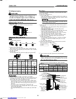
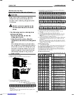
Detaching the Valve cover

Remove the 5 screws.

•  Pull the valve cover in the direction of the arrow, and remove it.

Valve cover


Refrigerant Piping Connection

Flaring

1. Cut the pipe with a pipe cutter.

Obliquity

Roughness

Warp

90°

2. Remove the burr inside of the pipe.
  When removing the burr, be careful so that chips do not fall into the pipe.
3. Remove the 

fl

 are nuts attached to the outdoor/indoor unit, then insert them 

into each of the pipes.

4. Flare the pipes.
  See the following table for the projection margin (A) and 

fl

 aring size (B).

Die

Pipe

B

A

Pipe

A

B

Flare Nut

Outside 

diameter

Thickness

Rigid 

(clutch 

type)

R410A 

tool

Imperial 

(wing 

nut type) 

R410A 

tool

Width 

across 

flat

Tighten 

torque

mm

mm

mm

mm

mm

mm

N•m

kgf•m

6.35

0.8

0 to 0.5

1.5 to 

2.0

9.1

17

14 to 

18

1.4 to 

1.8

9.52

0.8

0 to 0.5

1.5 to 

2.0

13.2

22

33 to 

42

3.3 to 

4.2

12.7

0.8

0 to 0.5

2.0 to 

2.5 

16.6

26

50 to 

62

5.0 to 

6.2

Pipe connection

1. Make wire and pipe connections for each indoor unit separately.
2. Align the centres of the connecting pipes and tighten the 

fl

 are nut as much 

as possible with your 

fi

 ngers, then tighten the nut using a torque wrench. 

Be sure to tighten the nut at the speci

fi

 ed torque value.

•  If you use one outdoor unit for several indoor units of a different class, 

connect the largest one 

fi

 rst A, then connect the rest in the order B to C.

•  Do not remove the 

fl

 are nuts for any ports you are not going to use for 

connection.

•  Do not leave the 

fl

 are nut unattached for a long period of time.

•  Use a different-diameter joint if the diameters of the connection port and 

connection piping are different.

•  Mount the different-diameter joint on the connection port of the outdoor 

unit.


Air Purge

From the sake of environmental protection, use a vacuum pump to extract 
the air during installation.
* Prepare a 4 mm hexagon wrench.
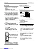
1. Connect a charge hose.

•  Make sure that the Handle Hi of the gauge manifold valve is closed fully.
•  Connect the port of the gauge manifold valve and the service port (Valve 

core (Setting Pin)) using the charge hose.

NOTE


If a control valve or charge valve is attached to the charge hose, leak 
of R410A refrigerant can be avoided.

2. Open the Handle Low of the gauge manifold valve fully, then operate the 

vacuum pump.
• Loosen the 

fl

 are nut of the at the gas end a little to make sure that air is 

taken in, then tighten the nut.

•  If you 

fi

 nd air is not taken in, make sure that the charge hose is 

connected to the port(s) securely.

•  Perform extraction for about 15 or more minutes and make sure that the 

compound pressure gauge reading is –101 kPa (–76 cmHg).

•  If the compound pressure gauge reading is not –101 kPa (–76 cmHg), 

there is a possibility air is being taken in from the port(s).

•  Make sure that the charge hose is connected to the port(s) securely.

3. Close the Handle Low of the gauge manifold valve fully, then stop 

operating the vacuum pump.
• Leave the gauge and pump as they are for 1 or 2 minutes, then make 

sure that the compound pressure gauge reading stays at –101 kPa 
(–76 cmHg).

•  You need not add refrigerant.

4. Disconnect the charge hose from the service port, then open the valve 

stem fully using a 4 mm hexagon wrench.

Hexagon wrench is 

required.

Service port cap

Valve stem cap

4 mm

5. Tighten the service valve stem cap and service port cap securely.

 CAUTION

Use a torque wrench and tighten the nut at 
the speci

fi

 ed torque value.

6. Tighten all the caps on the valves securely, then perform a gas leak 

inspection.

Service valve

Tighten torque

Valve stem cap

Service port cap

Type

mm

N•m

kgf•m

N•m

kgf•m

Liquid side

6.35

14 to 18

1.4 to 1.8

Gas side

9.52

14 to 18

1.4 to 1.8

14 to 18

1.4 to 1.8

12.7

33 to 42

3.3 to 4.2

14 to 18

1.4 to 1.8

Service valve at 

the liquid side

Service valve at 

the gas side

Service port

(Valve core 

(Setting pin))

Vacuum pump

Handle Hi
(Keep full closed)

Pressure gauge

Manifold valve

Charge hose
(For R410A only)

Vacuum pump 
adapter for counter-
flow preventation
(For R410A only)

Charge hose

(For R410A only)

Compound 

pressure gauge

–101 kPa (–76 cmHg)

Handle Low

1116691099_(01) EN.indd   8

1116691099_(01) EN.indd   8

9/22/15   5:59 PM

9/22/15   5:59 PM

Summary of Contents for RAS-2M14S3AV-E

Page 1: ... Manual Outdoor Unit Model name RAS 3M18S3AV E RAS 2M18S3AV E RAS 2M14S3AV E NOTE Descriptions about operations for the 3 indoor units in this manual are not applicable to RAS 2M18S3AV E and RAS 2M14S3AV E English Installation Manual Outdoor Unit ...

Page 2: ...ng 10 9 Test run 10 10 Pump down Operation 12 11 Troubleshooting 12 Please read this Installation Manual carefully before installing the Air Conditioner This Manual describes the installation method of the outdoor unit For installation of the indoor unit refer to the Installation Manual attached to the indoor unit IMPORTANT NOTICE For details on how to install the indoor units refer to the install...

Page 3: ...ity of severe injury 1 or death WARNING It indicates that incorrect use of this unit may cause severe injury or death CAUTION It indicates that incorrect use of this unit may cause personal injury 2 or property damage 3 1 A severe injury refers to blindness injury burns hot or cold electrical shock bone fracture or poisoning that leaves after effects and requires hospitalization or extended out pa...

Page 4: ...oles must be incorporated in the fixed wiring Turn off main power supply before attempting any electrical work Make sure all power switches are off Failure to do so may cause electric shock Connect the connecting cables correctly If the connecting cables are connected wrongly electric parts may be damaged Check the earth wire that it is not broken or disconnected before installation Do not install...

Page 5: ...s or the specified parts Failure to do so may cause the unit to fall water leakage fire or electrical shock After the installation work ensure that there is no leakage of refrigerant gas If the refrigerant gas leaks out of the pipe into the room and is heated by fire or something else from a fan heater stove or gas range it causes generation of poisonous gas Make sure the equipment is properly ear...

Page 6: ... disturb neighbours This appliance must be connected to the main power supply by means of a circuit breaker depending on the place where the unit is installed Failure to do so may cause electrical shock Follow the instructions in this installation manual to arrange the drain pipe for proper drainage from the unit Ensure that drained water is discharged Improper drainage can result in water leakage...

Page 7: ... combination of the indoor units which are operated The information in this specifications table applies for the combinations with the catalogue For operation read the owner s manual packed with the indoor unit Equipment complying with IEC 61000 3 12 1 If the air conditioner is used in conditions other than the above the safety protection functions may be activated Example of indoor unit class RAS...

Page 8: ... to the wiring and piping lengths on the inside rather than the outside When using an air conditioner under low outside temperature conditions Outside temp 5 C or lower In COOL mode prepare a duct or wind shield so that it is not affected by the wind Necessary Space for Installation If you need to install the outdoor unit in a location where there are some obstructions or a wall secure sufficient ...

Page 9: ...hexagon wrench 1 Connect a charge hose Make sure that the Handle Hi of the gauge manifold valve is closed fully Connect the port of the gauge manifold valve and the service port Valve core Setting Pin using the charge hose NOTE If a control valve or charge valve is attached to the charge hose leak of R410A refrigerant can be avoided 2 Open the Handle Low of the gauge manifold valve fully then oper...

Page 10: ...r refrigerant leaks may be required depending on European or local legislation Insulation of the Refrigerant Pipes Insulate the refrigerant pipes for liquid and gas separately Heat proof bubble polyethylene Gas Leak Inspection Perform a gas leak inspection for the flare nut connections valve stem connection and service port cap without fail Use a leak detector exclusively manufactured for R410A Fl...

Page 11: ...it Connect the connecting cable to the terminal as identified by the matching numbers on the terminal block of the indoor and the outdoor unit 5 Fix the wiring connections for the power source and each indoor unit securely using a cord clamp 6 Attach the terminal cover and the valve cover Stripping Length of connecting cable for outdoor unit 55 5 5 30 1 2 3 5 5 30 55 L N Earth wire Earth wire Powe...

Page 12: ... or less Also there is a possibility to misjudge if the indoor temperature becomes too low by cooling operation In that case execute the cooling operation for per room and check if the connection is normal Gas Leak Inspection Refer to the Gas Leak Inspection on page 9 Test run 1 If you perform the test run in summer start running in the cooling mode first to decrease the temperature of the room th...

Page 13: ...lve at the liquid end 9 Make sure that the compound pressure gauge reading is 101 kPa 76 cmHg 10 Close the valve stem of the service valve at the gas end 11 The refrigerants collection operation is finished in maximum 10 minutes After the collection is finished promptly stop the operation of all the indoor unit There are cases that the compressor restarts 12 When you want to start over the operati...

Page 14: ...144 9 Moo 5 Bangkadi Industrial Park Tivanon Road Tambol Bangkadi Amphur Muang Pathumthani 12000 Thailand 1116691099 ...

Reviews: