


FILE NO. SVM-07008
– 84 –
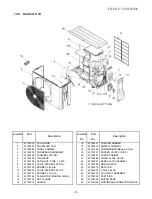
No.
Part name
Procedures
Remarks
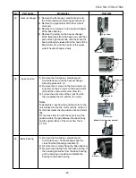
1) Perform work of item 1 of
1
.
2) Remove screw (ST1T
∅
4 x 10
s
1 pc.) of
the upper part of the front cabinet.
•
If removing the inverter cover in this
condition, the P.C. board can be checked.
•
If there is no space in the upper part of
the upper cabinet, perform work of
2
.
Be careful when checking the
inverter because high-voltage
circuit is incorporated in it.
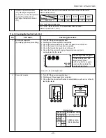
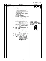
3) Perform discharging by connecting the
e
,
d
polarities by discharging resistance
(approx. 100
Ω
40W) or plug of soldering
iron to
e
,
d
terminals of the C13 (printed
“CAUTION HIGH VOLTAGE” is attached.)
electrolytic capacitor (760
µ
F/400 WV) on
the P.C. board.
Be careful to discharge the capacitor
because the electrolytic capacitor
cannot naturally discharge and
voltage remains depending on the
malfunction state in some cases.
NOTE :
This capacitor has mass capacity.
Therefore, it is dangerous that a
large spark generates if short-
circuiting between the
e
,
d
polarities
with screwdriver, etc. for discharging.
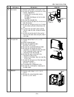
4) Perform the work of
2
.
5) Remove the screw (ST1T
∅
4 x 10
s
1 pc.)
fixing the main body and the inverter box.
6) Remove the lead wire from the holder on
the terminal block.
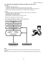
7) Disconnect the connectors of various lead
wires.
Requirement :
As each connector has a lock
mechanism, avoid removing the
connector by holding the lead wire,
but by holding the connector.
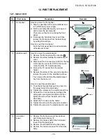
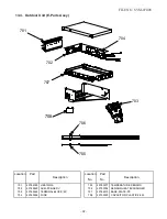
3
Inverter
assembly
The connector is one with lock,
so remove it while pushing the
part indicated by an arrow.
Be sure to remove the connector
by holding the connector, not by
pulling the lead wire.
PC board
(Soldered surface)
Inverter cover
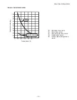
Discharging time
(Discharging period
10 seconds or more)
Plug of
soldering iron
Partition
Terminal
block
Summary of Contents for RAS-10N3ACV Series
Page 16: ...FILE NO SVM 07008 15 4 2 Outdoor Unit C L C L ...
Page 17: ... 16 FILE NO SVM 07008 5 WIRING DIAGRAM 5 1 Indoor Unit ...
Page 18: ...FILE NO SVM 07008 17 5 2 Outdoor Unit ...
Page 83: ...FILE NO SVM 07008 82 P C board layout Solder side ...
Page 94: ...FILE NO SVM 03008 87 TOSHIBA CARRIER CORPORATION ...


