

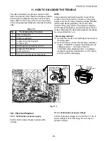
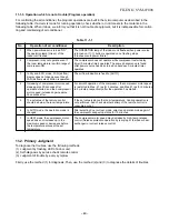


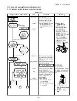

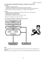


<Cause>
The IC is built in the indoor fan motor. Therefore the P.C. board is also mounted to the inside of the motor.
If the P.C. board is soldered imperfectly or the IC is defective, the fan motor may automatically rotate by turning
on power supply.
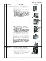
<Confirmation procedure>
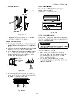
(1) Remove the front panel.
(2) Remove cover of the fan motor lead wires.
(3) Check DC voltage with CN31 connector while the fan rotating.
NOTE :
• Do not disconnect the connector while the fan rotates.
• Use a thin tester rod.
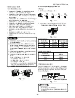
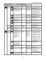
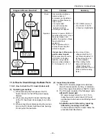
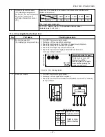
Indoor fan starts rotating when power supply breaker is turned “ON”.
(Check output voltage (DC) of the fan motor on P.C. board.)
Measure the voltage of the motor connector
CN31 pin
2
(GND : Black) and pin
5
(V line : Yellow)
under condition that the indoor fan rotates.
Above DC 0.4V
P.C. board is defective.
5 (Yellow)
4 (Blue)
3 (Yellow)
2 —
1 (Red)
Motor is defective.
Below DC 0.4V
(4) Indoor fan motor starts rotating by turning on power supply alone.
– 68 –
Yellow
Black
CN10
P.C. board
DC
6 (Blue)
FILE NO. SVM-0
7008
Summary of Contents for RAS-10N3ACV Series
Page 16: ...FILE NO SVM 07008 15 4 2 Outdoor Unit C L C L ...
Page 17: ... 16 FILE NO SVM 07008 5 WIRING DIAGRAM 5 1 Indoor Unit ...
Page 18: ...FILE NO SVM 07008 17 5 2 Outdoor Unit ...
Page 83: ...FILE NO SVM 07008 82 P C board layout Solder side ...
Page 94: ...FILE NO SVM 03008 87 TOSHIBA CARRIER CORPORATION ...


