


– 20 –
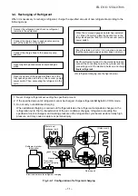
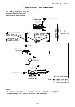
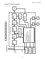
7. REFRIGERANT CYCLE DIAGRAM
7-1. Refrigerant Cycle Diagram
RAS-10SKV-E / RAS-10SAV-E
NOTE :
• The maximum pipe length of this air conditioner is 10 m. The addition charging of refrigevant is
Deoxidized copper pipe
Outer dia. : 9.52mm
Thickness : 0.8mm
NOTE :
Gas leak check position
Refrigerant flow (Cooling)
Refrigerant flow (Heating)
INDOOR UNIT
T1
TO
Temp. measurement
TC
TA
Indoor heat
exchanger
Cross flow fan
Deoxidized copper pipe
Outer dia. : 6.35mm
Thickness : 0.8mm
Sectional shape
of heat insulator
Allo
w
ab
le height
diff
erence :
10m
Allo
w
ab
le pipe length
P
Pressure measurement
Gauge attaching port
Vacuum pump connecting port
TD
4-way valve
(STF-0108Z)
Compressor
DA89X1C-23FZ
T2
Outdoor heat
exchanger
Temp. measurement
Propeller fan Refrigerant amount : 0.63kg
OUTDOOR UNIT
Muffler
Muffler
Ø1.
0
x
60
0
T E
Ø1.0 x 600
Min. : 1m
Chargeless : 10m
RAS-10SKV-A / RAS-10SAV-A
Max. : 10m
unnecessary because this air condition is design with charge-less specitication.
FILE NO. SVM-07008
Summary of Contents for RAS-10N3ACV Series
Page 16: ...FILE NO SVM 07008 15 4 2 Outdoor Unit C L C L ...
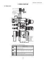
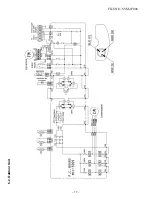
Page 17: ... 16 FILE NO SVM 07008 5 WIRING DIAGRAM 5 1 Indoor Unit ...
Page 18: ...FILE NO SVM 07008 17 5 2 Outdoor Unit ...
Page 83: ...FILE NO SVM 07008 82 P C board layout Solder side ...
Page 94: ...FILE NO SVM 03008 87 TOSHIBA CARRIER CORPORATION ...


