


–
28
–
Item
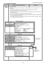
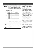
2. Indoor fan
motor control
Operation flow and applicable data, etc.
<In cooling operation>
(This operation controls the fan speed at indoor unit side.)
The indoor fan (cross flow fan) is operated by the phase-
control induction motor. The fan rotates in 5 stages in
MANUAL mode, and in 5 stages in AUTO mode, respec-
tively. (Table 1)
Description
* Symbols
UH
: Ultra High
H
: High
M+
:
M
: Medium
L+
: Low+
L
: Low
L-
: Low–
UL
: Ultra Low
SUL
: Super Ultra Low
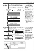
* The fan speed broadly varies due
to position of the louver, etc.
The described value indicates one
under condition of inclining
downward blowing.
1) When setting the fan speed to L,
L+, M, M+ or H on the remote
controller, the operation is
performed with the constant
speed shown in Fig. 1.
2) When setting the fan speed to
AUTO on the remote controller,
revolution of the fan motor is
controlled to the fan speed level
shown in Fig. 2 and Table 1
according to the setup tempera-
ture, room temperature, and heat
exchanger temperature.
(Fig. 1)
(Fig. 2)
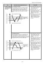
+2.5
Ta
[˚C]
+2.0
+1.5
+1.0
+0.5
Tsc
a
b
c
d
e
M+(WB)
*3
*4
*5
L(W6)
Air volume AUTO
L
L+
M
M+
H
W6
(L + M) / 2
W9
(M + H) / 2
WC
Indication
Fan speed
Fan speed setup
COOL ON
AUTO
MANUAL
*3 : Fan speed = (M + –L) x 3/4 + L
*4 : Fan speed = (M + –L) x 2/4 + L
*5 : Fan speed = (M + –L) x 1/4 + L
(Linear approximation
from M+ and L)
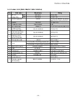
Fan speed
RAS-10SKV-E
level COOL HEAT DRY
RAS-10SKV-A
Fan speed
Air flow rate
(rpm)
(m
3
/h)
WF
UH
1350
607
WE
H
1300
576
WD
UH
M+
UH
1250
554
WC
H
H
1200
522
WB
M+
M
M+
1120
486
WA
M
1100
468
W9
M
L+
1040
444
W8
L
960
402
W7
L+
L-
L+
910
376
W6
L
L
880
360
W5
L-
UL
L-
830
334
W4
UL
UL
800
318
W3
SUL
SUL
700
266
W2
SUL
650
239
W1
600
213
(Table 1) Indoor fan and air flow rate
FILE NO. SVM-07008
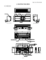
Summary of Contents for RAS-10N3ACV Series
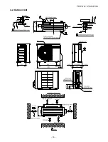
Page 16: ...FILE NO SVM 07008 15 4 2 Outdoor Unit C L C L ...
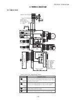
Page 17: ... 16 FILE NO SVM 07008 5 WIRING DIAGRAM 5 1 Indoor Unit ...
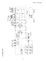
Page 18: ...FILE NO SVM 07008 17 5 2 Outdoor Unit ...
Page 83: ...FILE NO SVM 07008 82 P C board layout Solder side ...
Page 94: ...FILE NO SVM 03008 87 TOSHIBA CARRIER CORPORATION ...


