


67
◆
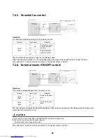
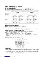
Address setting procedure 2
1
Set a system address for each system using SW 13 and 14 on the interface P.C. board on the
header outdoor unit of each system.
(Factory default: Address 1)
NOTE
Be sure to set a unique address on each system. Do not use a same address as another system (refrigerant line)
or a custom side.
Interface P.C. board on the header outdoor unit
Line address switches on the outdoor interface PC board (
{
: switch on,
✕
: switch off)
(Example)
Controlling 2 or more refrigerant lines as a group
System wiring
diagram
Outdoor
Indoor
Indoor
Indoor
Indoor
Outdoor
Remote
control
(Group control)
Not used for setup of line address (do not change setup.)
Line
address
Line
address
Summary of Contents for MMY-MAP0724HT6UL
Page 229: ...228 15Exploded Diagram Parts Price List SMMS i OUTDOOR UNIT MMY MAP0724HT6UL ...
Page 230: ...229 MMY MAP0724HT6UL ...
Page 232: ...231 SMMS i OUTDOOR UNIT MMY MAP0964HT6UL MMY MAP1144HT6UL ...
Page 233: ...232 MMY MAP0964HT6UL MMY MAP1144HT6UL ...
Page 237: ...236 SMMS i INV SERVICE PARTS LIST MMY MAP0724HT6UL 4 pieces PC board ...
Page 238: ...237 SMMS i INV SERVICE PARTS LIST MMY MAP0964HT6UL MMY MAP1144HT6UL 4 pieces PC board ...
Page 241: ...Copyright 2011 TOSHIBA CARRIER CORPORATION ALL Rights Reserved ...


