


118
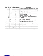
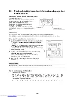
9-4. Check codes displayed on remote control and SMMS-
i outdoor unit (7-segment display on I/F board) and
locations to be checked
For other types of outdoor units, refer to their own service manuals.
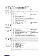
Check code
Location
of
detection
Description
System status
Error detection condition(s)
Check items (locations)
Wired
remote
control
Outdoor 7-segment display
Check
code
Sub-code
E01
–
–
Remote
control
Indoor-remote
control
communication
error
(detected at
remote control
end)
Stop of
corresponding
unit
Communication between indoor
P.C. board and remote control is
disrupted.
• Check remote control inter-unit
tie cable (A/B).
• Check for broken wire or
connector bad contact.
• Check indoor power supply.
• Check for defect in indoor P.C.
board.
• Check remote control address
settings
(when two remote controls are in
use).
• Check remote control P.C. board.
E02
–
–
Remote
control
Remote control
transmission
error
Stop of
corresponding
unit
Signal cannot be transmitted from
remote control to indoor unit.
• Check internal transmission
circuit of remote control.
--- Replace remote control as
necessary.
E03
–
–
Indoor
unit
Indoor-remote
control
communication
error
(detected at
indoor end)
Stop of
corresponding
unit
There is no communication from
remote control (including wireless)
or “1:1 Model” Connection Interface.
• Check remote control and “1:1
Model” Connection Interface
wiring.
E04
–
–
Indoor
unit
Indoor-outdoor
communication
circuit error
(detected at
indoor end)
Stop of
corresponding
unit
Indoor unit is not receiving signal
from outdoor unit.
• Check order in which power was
turned on for indoor and outdoor
units.
• Check indoor address setting.
• Check indoor-outdoor tie cable.
• Check outdoor termination
resistance setting (SW30, Bit 2).
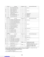
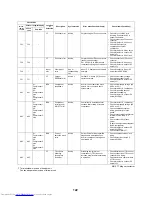
E06
E06
No. of indoor
units from
which signal is
received
normally
I/F
Dropping out of
indoor unit
All stop
Indoor unit initially communicating
normally fails to return signal for
specified length of time.
• Check power supply to indoor
unit.
(Is power turned on?)
• Check connection of indoor-
outdoor communication cable.
• Check connection of
communication connectors on
indoor P.C. board.
• Check connection of
communication connectors on
outdoor P.C. board.
• Check for defect in indoor P.C.
board.
• Check for defect in outdoor P.C.
board (I/F).
–
E07
–
I/F
Indoor-outdoor
communication
circuit error
(detected at
outdoor end)
All stop
Signal cannot be transmitted from
outdoor to indoor units for 30
seconds continuously.
• Check outdoor termination
resistance setting (SW30, Bit 2).
• Check connection of indoor-
outdoor communication circuit.
E08
E08
Duplicated
indoor address
Indoor
unit
I/F
Duplicated
indoor address
All stop
More than one indoor unit is
assigned same address.
• Check indoor addresses.
• Check for any change made to
remote control connection
(group/individual) since indoor
address setting.
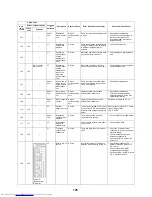
E09
–
–
Remote
control
Duplicated
master remote
control
Stop of
corresponding
unit
In two remote control configuration
(including wireless), both controllers
are set up as master. (Header
indoor unit is shut down with alarm,
while follower indoor units continue
operating.)
• Check remote control settings.
• Check remote control P.C.
boards.
E10
–
–
Indoor
unit
Indoor inter-
MCU
communication
error
Stop of
corresponding
unit
Communication cannot be
established/maintained upon
turning on of power or during
communication.
• Check for defect in indoor P.C.
board
Summary of Contents for MMY-MAP0724HT6UL
Page 229: ...228 15Exploded Diagram Parts Price List SMMS i OUTDOOR UNIT MMY MAP0724HT6UL ...
Page 230: ...229 MMY MAP0724HT6UL ...
Page 232: ...231 SMMS i OUTDOOR UNIT MMY MAP0964HT6UL MMY MAP1144HT6UL ...
Page 233: ...232 MMY MAP0964HT6UL MMY MAP1144HT6UL ...
Page 237: ...236 SMMS i INV SERVICE PARTS LIST MMY MAP0724HT6UL 4 pieces PC board ...
Page 238: ...237 SMMS i INV SERVICE PARTS LIST MMY MAP0964HT6UL MMY MAP1144HT6UL 4 pieces PC board ...
Page 241: ...Copyright 2011 TOSHIBA CARRIER CORPORATION ALL Rights Reserved ...


