background image

GR

NL

PT

ES

IT

DE

FR

RU

SI

SK

LV

CS

TR

EN

21-EN

Installation Manual

–21–

Toshiba 1112750201 (EN)



Change of lighting time of fi lter sign

According to the installation condition, the lighting 
time of the fi lter sign (Notifi cation of fi lter cleaning) 
can be changed. 
Follow to the basic operation procedure

(

1


2


3


4


5


6

) .

•  For the CODE No. in Procedure 

3

, specify [01]. 

•  For the [SET DATA] in Procedure 

4

, select the SET 

DATA of fi lter sign lighting time from the following 
table.



To secure better effect of heating

When it is diffi cult to obtain satisfactory heating due to 
installation place of the indoor unit or structure of the 
room, the detection temperature of heating can be 
raised. Also use a circulator, etc. to circulate heat air 
near the ceiling. 
Follow to the basic operation procedure
(

1


2


3


4


5


6

) .

•  For the CODE No. in Procedure 

3

, specify [06]. 

•  For the SET DATA in Procedure 

4

, select the SET 

DATA of shift value of detection temperature to be set 
up from the table below.

Procedure 

3


Using “TEMP.” 

 / 

 buttons, specify CODE No.

[

].

Procedure 

4


Using timer “TIME.” 

 / 

 buttons, select SET DATA 

[

].

Procedure 

5


Push 

 button. When the display changes from fl ashing 

to lit, the setup is completed. 
•  To change settings of another indoor unit, repeat from 

Procedure 

2

•  To change other settings of the selected indoor unit, 

repeat from Procedure 

3

 Use   button to clear the settings. 
 

To make settings after 

 button was pushed, repeat 

from Procedure 

2

Procedure 

6


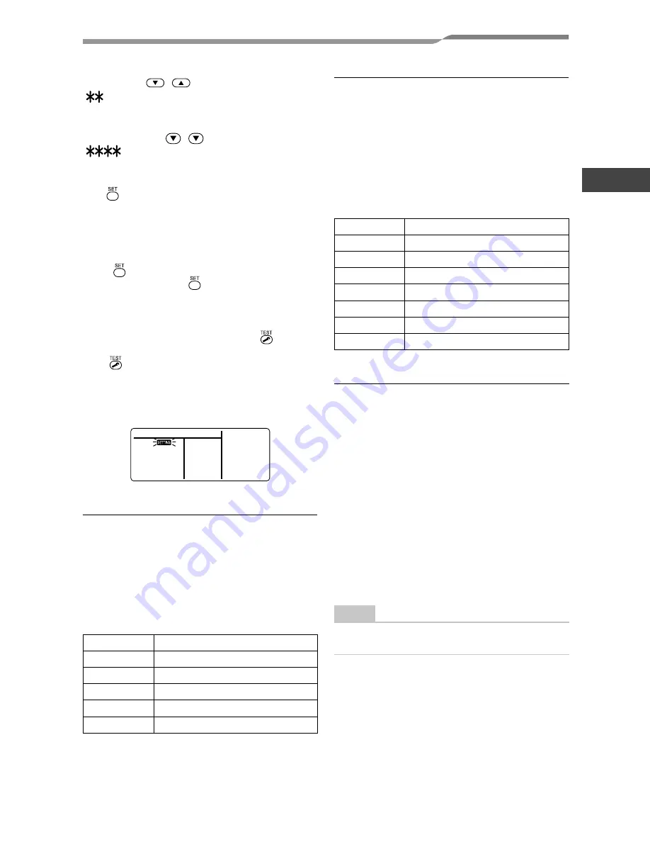
When settings have been completed, push 

 button to 

determine the settings. 
When 

 button is pushed, “SETTING” fl ashes and then 

the display content disappears and the air conditioner 
enters the normal stop mode. 
(While “SETTING” is fl ashing, no operation of the 
remote controller is accepted.)

SET DATA

Filter sign lighting time

0000

None

0001

150H (Factory setting)

0002

2500H

0003

5000H

0004

10000H

SET DATA

Detection temp shift value

0000

 No shift

0001

+1°C

0002

+2°C

0003

+3°C (Factory setting)

0004

+4°C

0005

+5°C

0006

+6°C



Group control 

In a group control, a remote controller can control 
up to maximum 8 units. 
•  The wired remote controller only can control a group 

control. The wireless remote controller is unavailable 
for this control. 

•  For cabling procedure and cables of the individual line 

(Identical refrigerant line) system, refer to “Electric 
work” in this Manual. 

•  Cabling between indoor units in a group is performed 

in the following procedure. 


Connect the indoor units by connecting the remote 
controller inter-unit cables from the remote controller 
terminal blocks (A, B) of the indoor unit connected 
with a remote controller to the remote controller 
terminal blocks (A, B) of the other indoor unit. 
(Non-polarity) 

•  For address setup, refer to the Installation Manual 

attached to the outdoor unit.

NOTE 

Net work adapter (Model TCB-PCNT20E) can not 
connect to this air conditioner.

Summary of Contents for MML-AP0074NH-E

Page 1: ...me Console Type MML AP0074NH E MML AP0074NH TR MML AP0094NH E MML AP0094NH TR MML AP0124NH E MML AP0124NH TR MML AP0154NH E MML AP0154NH TR MML AP0184NH E MML AP0184NH TR Ελληνικά Εγχειρίδιο Εγκατάστασης 197 Nederlands Installatiehandleiding 169 Português Manual de Instalação 141 Español Manual de Instalación 113 Italiano Manuale di Installazione 85 Deutsch Installationshandbuch 57 Français Manuel...

Page 2: ......

Page 3: ...NEW REFRIGERANT This Air Conditioner is a new type which adopts a new refrigerant HFC R410A instead of the conventional refrigerant R22 in order to prevent destruction of the ozone layer Contents 1 PRECAUTIONS FOR SAFETY 4 2 ACCESSORY PARTS 6 3 SELECTION OF INSTALLATION PLACE 7 4 INSTALLATION OF INDOOR UNIT 9 5 CUTTING A HOLE AND MOUNTING INSTALLATION PLATE 10 6 PIPING AND DRAIN HOSE INSTALLATION ...

Page 4: ...n relocation and removal has the qualifications pertaining to this refrigerant handling and piping work as stipulated by the local laws and regulations and he or she is a person who has been trained in matters relating to refrigerant handling and piping work on the air conditioners made by Toshiba Carrier Corporation or alternatively he or she has been instructed in such matters by an individual o...

Page 5: ...f the unit Doing so may result in injury Work undertaken Protective gear worn All types of work Protective gloves Safety working clothing Electrical related work Gloves to provide protection for electricians and from heat Insulating shoes Clothing to provide protection from electric shock Transportation of heavy objects Shoes with additional protective toe cap Repair of outdoor unit Gloves to prov...

Page 6: ...measures Accumulation of highly concentrated refrigerant may cause an oxygen deficiency accident Do not install the air conditioner in a location that may be subject to a risk of exposure to a combustible gas If a combustible gas leaks and becomes concentrated around the unit a fire may occur When transporting the air conditioner wear shoes with additional protective toe caps Do not place any comb...

Page 7: ...k check that the front panel of the indoor unit and service panel of the outdoor unit are closed and set the circuit breaker to the ON position You may receive an electric shock if the power is turned on without first conducting these checks When you have noticed that some kind of trouble such as when an error display has appeared there is a smell of burning abnormal sounds are heard the air condi...

Page 8: ...mer refrigerant or refrigerating oil does not enter the refrigerating cycle To prevent charging an incorrect refrigerant and refrigerating oil the sizes of connecting sections of charging port of the main unit and installation tools are changed from those for the conventional refrigerant Accordingly the exclusive tools are required for the new refrigerant R410A For connecting pipes use new and cle...

Page 9: ...e the performance generate mist or dew drop or deform or damage resin parts Place where organic solvent is used nearby Place close to a machine generating high frequency Place where the discharged air blows directly into the window of the neighbour house Outdoor unit Place where noise of the outdoor unit is easily transmitted When install the outdoor unit on the boundary with the neighbour pay due...

Page 10: ... case of right or left piping Heat insulator Air filter Installation place A place which provides the spaces around the indoor unit as shown in the diagram A place where there are no obstacles near the air inlet and outlet A place which allows easy installation of the piping to the outdoor unit A place which allows the front panel to be opened CAUTION Direct sunlight to the indoor unit s wireless ...

Page 11: ...human injury Perform a specified installation work to guard against strong wind or earthquake An incomplete installation can cause accidents by the units falling and dropping REQUIREMENT Strictly comply with the following rules to prevent damage of the indoor units and human injury Do not put a heavy article on the indoor unit Even units are packaged Carry in the indoor unit as it is packaged if p...

Page 12: ...HOLE AND MOUNTING INSTALLATION PLATE PLATE CAUTION When installing the installation plate with a mounting screw do not use the anchor bolt hole Otherwise the unit may fall down and result in personal injury and property damage CAUTION Failure to firmly install the unit may result in personal injury and property damage if the unit falls In case of block brick concrete or similar type walls make 5 m...

Page 13: ... pipe for proper drainage from the unit Improper drainage can result in dew dropping Front panel Air inlet grille Hook Do not rise the drain hose Do not form the drain hose into a wavy shape Do not put the drain hose end into water Do not put the drain hose end in the drainage ditch NOTE The hole should be made at a slight downward slant on the outdoor side NOTE When bending the connection piping ...

Page 14: ...istance with indoor unit as shown in the following figure 2 Installation using the supporting plate To install into the existing wall hole if it is impossible to keep 20 30 mm of depth use the supporting plate for securing the distance Arrange the screw positions and supporting plate as shown in the figure Be sure to switch to wall burying mode Rear screws potion Field supply Screw holes Field sup...

Page 15: ...ge Connected points MML AP007 to AP012 type AP015 to AP018 type Gas side 9 5 12 7 Liquid side 6 4 6 4 Outer dia of copper pipe R410A tool used Conventional tool used R410A R410A 6 4 9 5 0 to 0 5 1 0 to 1 5 12 7 Outer dia of copper pipe R410A 6 4 9 1 9 5 13 2 12 7 16 6 Projection margin in flaring B Unit mm Rigid Clutch type Flaring dia meter size A Unit mm 0 0 4 A In case of flaring for R410A with...

Page 16: ... or ground wires for telephone wires 3 Appliance shall be installed in accordance with national wiring regulations Capacity shortage of power circuit or incomplete installation may cause an electric shock or a fire CAUTION If incorrect incomplete wiring is carried out it will cause an electrical fire or smoke Be sure to install an earth leakage breaker that is not tripped by shock waves If an eart...

Page 17: ...ing This wiring is not required when using the supplied wireless remote controller For wiring remote controllers a 2 core non polarity wire must be used Power supply 220 240V 50Hz 220V 60Hz Power supply switch Earth leakage breaker or power supply wiring fuse rating for indoor units should be selected by the accumulated total current values of the indoor units Power supply wiring Below 50 m 2 5 mm...

Page 18: ...or unit Follower outdoor unit Control wiring between outdoor units Control wiring between indoor and outdoor units Indoor unit Indoor unit Indoor unit Indoor unit Earth Earth Earth Earth Indoor power supply Earth leakage breaker power switch Pull box Pull box Pull box Remote controller Remote controller Remote controller Address setup Set up the addresses as per the Installation Manual supplied wi...

Page 19: ... form the front 5 Insert the power supply wire fully into the terminal block and secure it tightly with screws Tighten torque 1 2 N m 0 12 kgf m 6 Clamp the power supply wire with the cord clamp 7 Attach the terminal cover with a screw CAUTION Be sure to refer to the wiring diagram attached inside the front panel Check local electrical cords and also any specific wiring instructions and limitation...

Page 20: ...move the LED BASE 4 Insert the control wire fully into the control Wired remote controller terminal block and secure it tightly with screws 5 Clamp the control wire with the cable clamp 6 Pass the banding band through the hole of the mount base 7 Band the control wire and the remote controller wire in the banding band 8 Attach the LED base terminal cover and front panel Connecting control wire and...

Page 21: ... the power supply wire faston terminal of the flow selector unit into the power supply terminal Secure the earth line with the earth screw 7 Connect the control wire connector of flow selector unit to the control wire 8 Clamp the power supply wire with the cord clamp 9 Attach the terminal cover with a screw 10 Take the control wire out of the cable slot on the rear panel so that it produces about ...

Page 22: ...ler separately as well 4 6 3 1 1 5 2 Procedure 1 Push button and TEMP button simultaneously for at least 4 seconds After a while the display flashes as shown in the figure Confirm that the CODE No is 10 If the CODE No is not 10 push button to erase the display content and repeat the procedure from the beginning No operation of the remote controller is accepted for a while after button is pushed Wh...

Page 23: ...re 3 Use button to clear the settings To make settings after button was pushed repeat from Procedure 2 Procedure 6 When settings have been completed push button to determine the settings When button is pushed SETTING flashes and then the display content disappears and the air conditioner enters the normal stop mode While SETTING is flashing no operation of the remote controller is accepted SET DAT...

Page 24: ...ler operate the unit as usual For the procedure of the operation refer to the attached Owner s Manual A forced test run can be executed in the following procedure even if the operation stops by thermo OFF In order to prevent a serial operation the forced test run is released after 60 minutes have passed and returns to the usual operation CAUTION Do not use the forced test run for cases other than ...

Page 25: ...10 seconds or more Pi sound is heard and the operation changes to a forced cooling operation After approx 3 minutes a cooling operation starts forcedly Check cool air starts blowing If the operation does not start check wiring again 2 To stop a test operation push button once again Approx 1 second The louver closes and the operation stops In case of wireless remote controller Forced test operation...

Page 26: ...story can be confirmed with the following procedure The trouble history is stored in memory up to 4 troubles The history can be confirmed from both operating status and stop status Procedure 1 When pushing and buttons at the same time for 4 seconds or more the following display appears If Service check is displayed the mode enters in the trouble history mode 01 Order of trouble history is displaye...

Page 27: ...ntroller display Outdoor 7 segment display Sensor block display of receiving unit Auxiliary code OPERATION TIMER PRE DEF Flash E01 Communication error between indoor and remote controller Detected at remote controller side Remote controller E02 Remote controller transmission error Remote controller E03 Communication error between indoor and remote controller Detected at indoor side Indoor E04 Comm...

Page 28: ... F22 ALT TD3 sensor error I F F23 F23 ALT Ps sensor error I F F24 F24 ALT Pd sensor error I F F29 SIM Indoor other error Indoor F31 F31 SIM Indoor EEPROM error I F H01 H01 01 Comp 1 side 02 Comp 2 side 03 Comp 3 side Compressor break down IPDU H02 H02 01 Comp 1 side 02 Comp 2 side 03 Comp 3 side Magnet switch error Overcurrent relay operation Compressor trouble lock MG SW Overcurrent relay IPDU H0...

Page 29: ...or fan motor error Indoor P03 P03 ALT Discharge temp TD1 error I F P04 P04 01 Comp 1 side 02 Comp 2 side 03 Comp 3 side ALT High pressure SW system operation IPDU P05 P05 00 01 Comp 1 side 02 Comp 2 side 03 Comp 3 side ALT Phase missing detection Power failure detection Inverter DC voltage error comp Inverter DC voltage error comp Inverter DC voltage error comp I F P07 P07 01 Comp 1 side 02 Comp 2...

Page 30: ...an 0E Comp 2 Comp 3 Fan 0F Comp 1 Comp 2 Comp 3 Fan Check code Wireless remote controller Check code name Judging device Central control device indication Outdoor 7 segment display Sensor block display of receiving unit Auxiliary code OPERATION TIMER PRE DEF Flash C05 Sending error in TCC LINK central control device TCC LINK C06 Receiving error in TCC LINK central control device TCC LINK C12 Batch...

Page 31: ...ntration limit kg m3 The concentration limit of R410A which is used in multi air conditioners is 0 44 kg m3 NOTE 1 If there are 2 or more refrigerating systems in a single refrigerating device the amounts of refrigerant should be as charged in each independent device e g charged amount 15 kg Outdoor unit e g charged amount 10 kg Room A Room B Room C Room D Room E Room F Indoor unit For the amount ...

Page 32: ...or check method refer to Applicable controls in this sheet Filter sign lighting time CODE No 01 NO CHANGE NONE 0000 150H 0001 2500H 0002 5000H 0003 10000H 0004 Filter sign lighting time CODE No 01 NO CHANGE NONE 0000 150H 0001 2500H 0002 5000H 0003 10000H 0004 Filter sign lighting time CODE No 01 NO CHANGE NONE 0000 150H 0001 2500H 0002 5000H 0003 10000H 0004 Filter sign lighting time CODE No 01 N...

Reviews: