116
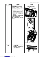
Drawing port of fan motor lead wires should be this position.
Determine the lead drawing port position so that motor band
(Right) does not come to contact with fan motor drawing port.
Draw out fan motor lead wire from here.
( )
Fixing
screws
Motor band (Right)
Motor band (Right)
Set screw
Cross-flow fan
Fixing screws
No.
W
Part name
Fan motor
Procedure
1) Perform work of item
R
.
2) Perform work of item
T
.
3) Loosen the set screw of the cross-flow fan
from the discharge port.
4) Take off fixing screws (2 pcs) to remove the
motor band (Right).
5) Pull out the fan motor outward.
Remarks
Assemble the fan motor as shown below.
X
1) Perform works of items
R
and
T
.
2) Take off fixing screws (2 pcs.) at the left side
of the end plate of the heat exchanger, and
then take off fixing screws (2 pcs.) of the
bearing base.
3) Make the left side of the heat exchanger float
slightly, and then remove the bearing base.
4) Loosen set screw of the cross-flow fan from
the discharge port.
5) Take off fixing screws (2 pcs.) to remove the
motor band (Right).
Cross-flow fan
* Remove set screw from gap of thermal
insulator.
FILE NO. SVM-05052
Summary of Contents for MMK-AP0072H
Page 125: ...TOSHIBA CARRIER CORPORATION ...


