background image

51

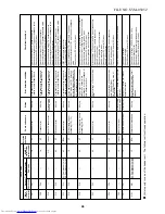
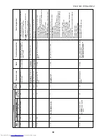
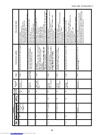
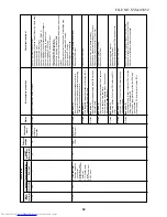
Chec

k code

Main

remote

contr

oller

P07

P12

P13

P15

P17

P19

Outdoor 7-segment displa

y

Chec

k code

Sub-code

P07

0

1

:

Compressor

1 side

0

2

:

Compressor

2 side

——

P13

P15

0

1

:

TS condition

02:

 TD 

condition

P17

P19

Detected

outdoor unit No

.

AI-NET

central contr

ol

remote contr

oller

1C

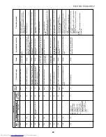
11

47

AE

AE

bb

8

Detected

position

IPDU

I/F

Indoor

I/F

I/F

I/F

I/F

I/F

Check code

name

Heat sink

o

v

erheat error

Indoor f

a

n

motor error

Outdoor liquid

bac

k detection

error

Gas leak

detection

(TS1 condition)

Gas leak

detection

(TD condition)

Discharge

temp TD2 

error

4-w

a

y

 v

alv

e

oper

ation error

Status

All stop

Corresponding

unit only stops

.

All stop

All stop

All stop

All stop

All stop

Err

or detection condition

IGBT b

uilt-in temp sensor (TH) w

as o

v

erheated.

The v

alue of motor speed de

viated from

target v

alue w

as detected f

or cer

tain time

.

O

v

er-current protection oper

ated.

<In cooling>

While the system is oper

ating in COOL mode

, a

high pressure v

alue w

as detected in f

ollo

w

e

r

unit in which compressor did not oper

ate

.

<In heating>

While the system is oper

ating in HEA

T mode

,

outdoor PMV of which opening deg

ree w

a

s

100p or less f

or a cer

tain time

.

Suction temp e

xceeded the judgment standard

temp f

or 10 min

utes or more

.

<TS err

or judgment standar

d temperature>

In cooling oper

ation:

 60

°C or higher

In heating oper

ation:

 40

°C or higher

Discharge temper

ature 

TD1 or 

TD2 w

a

s

contin

uously 108

°C or higher f

or 10 min

utes

.

Discharge temper

ature (TD2) e

xceeded 115

°C.

When abnor

mal refr

iger

ating cycle data w

a

s

detected in heating

Chec

k item (position)

Chec

k po

w

er v

oltage

.

Chec

k outdoor f

an system error

.

Chec

k clogging of heat sink cooling duct.

Chec

k fixation betw

een IGBT and heat sink.

(Chec

k scre

wing and contact.)

Chec

k IPDU error

.(IGBT b

uilt-in temp sensor (TH) error)

Chec

k connection of f

an connector and wir

ing.

Chec

k f

an motor error

.

Chec

k indoor P

.C

. board error

.

Chec

k influence of outside air control.

Chec

k indoor type code (DN=10) and the capacity code (DN=11).

Chec

k full close oper

ation of outdoor PMV (1, 2).

Chec

k Pd and Ps sensor error

.

Chec

k clogging of SV2 circuit.

Chec

k clogging of balance pipe

.

Chec

k clogging of SV3B circuit.

Chec

k outdoor P

.C

. board (I/F) error

.

Chec

k capillar

y clogging of oil retur

n circuit from oil separator

.

Chec

k leakage of chec

k v

alv

e of the main discharge pipe

.

Chec

k refr

iger

ant shor

tage

.

Chec

k full open of outdoor ser

vice v

alv

es (gas side

, liquid side).

Chec

k outdoor PMV clogging (PMV1, 2).

Chec

k char

acter

istics of 

TS1 sensor resistance v

alue

.

Chec

k 4-w

a

y

 v

alv

e error

.

Chec

k leakage of SV4 circuit.

Chec

k refr

iger

ant shor

tage

.

Chec

k outdoor PMV clogging (PMV1, 2).

Chec

k char

acter

istics of 

TD1, 

TD2 sensor resistance v

alue

.

Chec

k indoor air filter clogging.

Chec

k pipe clogging.

Chec

k SV4 circuit (V

alv

e leakage

, misinstallation)

Chec

k full opening of outdoor ser

vice v

alv

es

(gas side

, liquid side).

Chec

k clogging of outdoor PMV (PMV1, 2).

Chec

k char

acter

istics of 

TD2 sensor resistance v

alue

.

Chec

k 4-w

a

y

 v

alv

e error

.

Chec

k leakage of SV42 circuit.

Chec

k SV4 circuit.

(Miscab

ling and misinstallation of SV41 and SV42)

Error of 4-w

a

y

 v

alv

e error

Chec

k coil error and connector connection of 4-w

a

y v

alv

e

.

Chec

k char

acter

istics of 

TS1/TE1 sensor resistance v

alue

.

Chec

k char

acter

istics of Pd, Ps pressure sensor output v

oltage

.

Chec

k misconnection of 

TE1 and 

TL sensors

.

FILE NO. SVM-05052

Summary of Contents for MMK-AP0072H

Page 1: ...ToMo SERVICE MANUAL High WallType MMK AP0072H MMK AP0092H MMK AP0122H This Service Manual describes contents of the new High Wall indoor unit For the outdoor unit refer to the Manual with FILE NO A03 009 The service parts will be supplied by TCTC ...

Page 2: ...PARTS RATING 10 4 REFRIGERANTING CYCLE DIAGRAM 23 5 CONTROL OUTLINE 24 6 APPLIED CONTROL 30 7 TROUBLESHOOTING 37 8 CONFIGURATION OF CONTROL CIRCUIT 111 9 HOW TO REPLACE MAIN PARTS 113 10 REPLACEMENT OF SERVICE INDOOR P C BOARD 118 11 EXPLODED VIEWS AND PARTS LIST 123 2 FILE NO SVM 05052 ...

Page 3: ...s other refrigerant R22 etc never use R410A If different types of refrigerant are mixed abnormal high pressure generates in the refriger ating cycle and an injury due to breakage may be caused Do not charge refrigerant additionally If charging refrigerant additionally when refrigerant gas leaks the refrigerant composition in the refrigerating cycle changes resulted in change of air conditioner cha...

Page 4: ...large amount of charged refrigerant such as a multi air conditioner in a sub room it is necessary that the density does not the limit even if the refrigerant leaks If the refrigerant leaks and exceeds the limit density an accident of shortage of oxygen is caused For the installation moving reinstallation work follow to the Installation Manual If an incorrect installation is done a trouble of the r...

Page 5: ... not mix in because pipes are affected by impurities such as water oxide scales oil etc Use the clean pipes Be sure to brazing with flowing nitrogen gas Never use gas other than nitrogen gas 4 For the earth protection use a vacuum pump for air purge 5 R410A refrigerant is azeotropic mixture type refrigerant Therefore use liquid type to charge the refrigerant If using gas for charging composition o...

Page 6: ...Vacuum evacuating Refrigerant charge Refrigerant charge Gas leakage check Refrigerant charge Conventional air conditioner installation Whether new equipment can be used with conventional refrigerant Yes Note 1 No No Yes Yes No Yes No Whether conven tional equipment can be used Note 1 Note 1 No No No Yes No No No 1 Vacuum pump Use vacuum pump by attaching vacuum pump adapter 2 Torque wrench 3 Pipe ...

Page 7: ...Service port Service port Ø6 4 Copper pipe Ø6 4 Copper pipe Fully tightened Fully tightened Reducing valve Nitrogen gas Valve fully closed liquid side Valve fully closed balance Connected to other terminal units Charge the refrigerant as below Recover the refrigerant and check there is no refrigerant in the equipment Leave it as it is for 1 to 2 minutes and check the indicator of the compound gaug...

Page 8: ... 275 790 Hock for insulation plate Refrigerant pipe connecting port Gas side Ø9 5 Refrigerant pipe connecting port Liquid side Ø6 4 Drain pipe 60 54 5 208 60 54 5 48 790 48 Knockout 60 Note All dimensions are in mm Installation space 100mm or more 170mm or more 300mm or more 170mm or more For attached Flow Selector unit of heat recovery model FILE NO SVM 05052 ...

Page 9: ...or TC2 Heat exchanger sensor TCJ Thermo sensor TA Wierd remote controller Sold Separately CN100 BRW CN101 BLU CN103 GRN CN102 YEL CN104 WHI CN1 WHI BLK DC 15V DC 0V DC 12V DC 7V BLK HBS BLK CN22 F S CN82 BLU WHI 1 3 1 3 10 9 8 7 6 5 4 3 2 1 10 9 8 7 4 3 2 1 2 3 4 5 6 7 10 11 1 2 3 4 5 6 1 2 3 4 5 1 2 3 4 5 6 1 2 3 4 5 6 2 3 4 5 6 1 2 3 4 5 6 1 3 4 5 6 1 3 4 5 6 7 8 9 9 5 4 3 2 1 5 4 3 2 1 6 5 4 3 ...

Page 10: ... 600mm Ø6 800mm Ø6 800mm Specications Output Rated 30W 280 340V DC 10kΩ at 25 C 10kΩ at 25 C 10kΩ at 25 C 10kΩ at 25 C 3 2 Name of Each Part Air inlet grille Air in the room is sucked from here Earth screw Earth screws are provided in the electric parts box Air filter Removes dust and trash Air filter is provided in the air inlet grille Air outlet Air outlet flap Change the direction of the air to...

Page 11: ...s indication is displayed the indoor fan stops or the mode enters in LOW 13 No function display Displayed if there is no function even if the button is pushed 14 Air volume select display The selected air volume mode is displayed AUTO HIGH MED LOW 15 Stand by display Displayed when unit cannot start cooling operation because other indoor units are being heating operation Display section Operation ...

Page 12: ...IT and AUTO flap button UNIT Select a unit No Automatic swing or adjust flap angle 7 Operation lamp Lamp is lit during the operation Lamp is off when stopped Although it flashes when operating the protection device or abnormal time 8 button When the button is pushed the operation starts and it stops by pushing the button again When the operation has stopped the opera tion lamp and all the displays...

Page 13: ...One push of the button and the display changes in the order shown on the right In HEAT mode if the room temperature reaches to the set temperature the outdoor unit stops and the air flow becomes LOW and the air volume decreases In the defrost mode the fan stops so that cool air is not discharged and PRE DEF is displayed 3 Select air volume with FAN button One push of the button and the display cha...

Page 14: ...select the Auto mode it is unnecessary to set the fan speed The FAN speed display will show AUTO and the fan speed will be automatically controlled After the heating operation has stopped FAN operation may continue for approx 30 seconds When the room temperature reaches the set temperature and the outdoor unit stops the super low wind is discharged and the air volume decreases excessively During d...

Page 15: ...in the unit of 0 5 hr 30 minutes The maximum set time is 72 0 hr For every push of button the set time decreases in the unit of 0 5 hr 30 minutes The minimum set time is 0 5 hr 3 Push SET button SET DATA display disappears and display goes on When ON timer is activated time is displayed and after time of the timer has been up displays other than ON disappear Cancel of timer operation 4 Push CL but...

Page 16: ...ir conditioner in a place where it is usually exposed to strong wind such as in seaside area or on the roof or upper floor of a building Do not install the air conditioner in a place where sulfureous gas generated such as in a spa Do not install the air conditioner in a vessel or mobile crane Be careful with noise or vibrations Do not install the air conditioner in a place where noise by outdoor u...

Page 17: ...oner If the protective device works the operation stops and the operation lamp flashes When the protective device works the indication and the check code are displayed on the display section of the remote controller In the following cases the protective device may work In cooling operation The suction port or discharge port of the outdoor unit is closed A strong wind continuously blows to the disc...

Page 18: ...of the flap You can stop the flap at the desired position 3 Auto flap button UNIT Push UNIT to set up the air direction individually in each indoor unit Then the indoor unit No in a group control is displayed For the displayed indoor unit set up the air direction If the unit No is not displayed all the indoor units are operated at the same time Every pushing UNIT the display is ex changed as follo...

Page 19: ...efrosted water will be drained from the bottom plate of the outdoor unit Heating capacity In the heating operation the heat is absorbed from the outside and brought into the room This way of heating is called heat pump system When the outside temperature is too low it is recommended to use another heating apparatus in combination with the air conditioner Attention to snowfall and freeze on the out...

Page 20: ...ing by yourself Cleaning of the air filter and other parts of the air filter involves dangerous work in high places so be sure to have a service person do it Do not attempt it yourself Daily maintenance Open the air inlet grille Lift the air inlet grille up to the horizontal position Take hold of the left and right handles of the air filter and lift it up slightly then pull downward to take it out...

Page 21: ... the air inlet grille with a neutral deter gent for kitchen use and rinse it off with water 3 Wipe out water from the air inlet grille and dry it 4 Fit the left and right arms of the air inlet grille to the shafts on the two sides of the air conditioner and push in com pletely and then push in the center arm 5 Check that the center arm has been completely inserted and close the air inlet grille Pu...

Page 22: ...d an operation contrary to the setup operation is performed When fan operation stopped to prevent discharge of hot air Since refrigerant is flowed temporarily to prevent stay of oil or refrigerant in the stand by indoor unit sound of flowing refrigerant Kyururu or Shaa may be heard or white steam when other indoor unit operates in HEAT mode and cold air in COOL mode may be blow out Sound is genera...

Page 23: ...Connector CN082 6P Blue 1 Controls super heat in cooling operation 2 Controls under cool in heating operation 3 Recovers refrigerant oil in cooling operation 4 Recovers refrigerant oil in heating operation Connector CN104 2P White 1 Detects indoor suction temperature Connector CN100 3P Brown 1 Controls PMV super heat in cooling operation Connector CN101 2P Blue 1 Controls PMV under cool in heating...

Page 24: ...2 Operation select 3 Room temp control 1 Adjustment range Set temperature on remote controller C Wired type Wireless type In cooling drying 18 to 29 C 17 to 30 C In heating 18 to 29 C 17 to 30 C 2 From the item code 06 the setup temperature in heating operation can be corrected Setup data Setup temp correction 0 2 4 6 0 C 2 C 4 C 6 C Setup at shipment Setup data 2 Heating suction temperature shift...

Page 25: ...urns to the normal operation When the forced thermo OFF became S0 with continua tion of J zone operation of the the indoor fan in LOW L mode until it reaches the 1 zone It is reset when the following conditions are satisfied Reset conditions 1 TC1 12 C and TC2 12 C and TCJ 12 C 2 20 minutes passed after stop P1 Q1 TC1 TC2 TCJ 10 C 5 C 10 C 0 C 14 C 2 In cooling operation the air conditioner operat...

Page 26: ... of remaining heat 1 When the air conditioner stops in the HEAT mode drive the indoor fan with LOW mode for approx 30 seconds 12 Flap control 1 Flap position setup Wired type The flap position can be set up in the following operation range 13 Filter sign display None in wireless type Provided in the separately laid type TCB AX21E 1 The operation time of the indoor fan is integrated and stored in m...

Page 27: ...OL priority is set Outdoor I F P C board SW11 bit 1 is ON and the other indoor unit is under COOL DRY opera tion 2 HEAT standby is displayed until the above conditions are released Remarks goes on Not displayed on the wired type Item and display Operation and heating stand by goes on 15 Selection of central control mode 1 The contents which can be changed on the remote controller at indoor unit si...

Page 28: ... A operation the air conditioner will start the following opera tion The fan speed display will indicate AUTO and low speed will be used Cooling operation In the operation suppression zone where capacity is kept to the minimum overcooling is prevented by raising the temperature setting by 1 C after 1 hour and by 2 C after 2 hours of operation The room temperature is thus regulated between the oper...

Page 29: ...while the display flashes The mark is indicated and the setting is memo rized If you do not press the MEMO button within 3 seconds or if you press another button the MEMORY setting is cancelled Operation modes which can be memorized with the MEMO button are MODE Tempera ture FAN TIMER and Hi POWER Remarks Item MEMORY operation 19 PRESET operation To operate the air conditioner with the setting mem...

Page 30: ... button the indoor unit numbers in the group control are successively displayed In this time the fan of the selected indoor unit only is turned on 3 Specify the item code DN using the setup temperature and buttons 4 Select the setup data using the timer time and buttons When selecting the DN code to 33 change the temperature indication of the unit from C to F on the remote controller 5 Push SET bu...

Page 31: ...recommended 0000 Provided 0001 Not provided Automatic selection from connected outdoor unit 0000 Heat pump 0001 Cooling only No display of AUTO HEAT 0000 1 way air discharge cassette 0001 4 way air discharge cassette to 0037 0008 High Wall 0000 Unfixed 0001 to 0034 0001 No 1 unit to 0030 No 30 unit 0001 No 1 unit to 0064 No 64 unit 0000 Individual 0001 Header unit of group 0002 Follower unit of gr...

Page 32: ...trol items 1 Start Stop input signal Operation start stop in unit 2 Operation signal Output during normal operation 3 Error signal Output during alarm Serial communication error or indoor outdoor protective device operation 2 Wiring diagram using remote control interface TCB IFCB 4E Input IFCB 4E No voltage ON OFF serial signal Output No voltage contact for operation error display Contact capacity...

Page 33: ...firstly indicates the header indoor unit address in the group control In this time the fan of the selected indoor unit turns on 2 Every pushing UNIT button the indoor unit numbers in group control are displayed succes sively In this time the fan of the selected indoor unit only turns on 3 Using the setup temp or button specify the item code 4 Using the timer time or button select the setup data At...

Page 34: ...ard is taken out from the card switch box When the card switch box does not perform the above contact operation convert it using a relay with b contact 2 Operation Handle the wired remote controller switch in the following procedure Use the wired remote controller switch during stop of the system 1 Push concurrently SET CL buttons for 4 seconds or more 2 Using the setup temp or button specify the ...

Page 35: ...Remote controller CN41 DC 20V Fan drive CN32 DC 12V Louver CN33 DC 20V DC fan input output CN210 Terminator resistor provided not provided Remote controller A B switch SW01 Display output Wireless sensor CN213 DC 5V Option power supply CN309 AC 200V Central control CN40 DC 5V TCJ sensor CN102 DC 5V Microcomputer operation LED D02 TC sensor CN101 DC 5V EEPROM IC10 Inter unit wire CN67 AC 200V FILE ...

Page 36: ...rost output ON during defrosting of outdoor unit 3 Thermo ON output ON when Real thermo ON Comp ON 4 Cooling output ON when operation mode is cooling line Cool Dry Cooing Heating AUTO cooling 5 Heating output ON when operation mode is heating line Heat Cooling Heating AUTO heating Optional output CN60 6 Fan output ON when indoor fan is ON 1 DC12V COM 2 DC12V COM Outside error input CN80 3 Filter O...

Page 37: ... after compressor OFF Is not thermostat OFF Is not the fan operating or timer Is not the system initially communicating Is not the cold draft prevention being controlled in heating operation Is not low cooling operation being controlled Is not a defrost operation being performed Is not after heat elimination operation being controlled after heating opera tion Is not auxiliary unit or remote contro...

Page 38: ...ommunication between outdoor units E15 E16 00 Capacity over 01 No of connected units E19 00 No header unit 02 Two or more header units E20 01 Outdoor of other line connected 02 Indoor of other line connected E23 E25 E26 No of outdoor units which received signal normally E28 Detected outdoor unit number 01 IPDU1 error 02 IPDU2 error 03 IPDU1 2 error E31 04 Fan IPDU error 05 IPDU Fan IPDU error 06 I...

Page 39: ...F06 F07 F08 F10 F12 F13 F15 F16 F23 F24 F29 F31 H01 H02 H03 H04 H06 H07 H08 H14 H16 L03 L04 L05 L06 L07 L08 L09 L10 L20 L28 L29 L30 Outdoor 7 segment display Sub code F04 F05 F06 F07 F08 F12 F13 01 Comp 1 side 02 Comp 2 side F15 F16 F23 F24 F31 H01 01 Comp 1 side 02 Comp 2 side H02 01 Comp 1 side 02 Comp 2 side H03 01 Comp 1 side 02 Comp 2 side H04 H06 H07 01 TK1 sensor error H08 02 TK2 sensor err...

Page 40: ...overheat error Indoor fan motor error Outdoor liquid back detection error Gas leak detection Discharge tempTD2 error 4 way valve inverse error High pressure protective operation Outdoor fan IPDU error G TR short protection error Comp position detective circuit system error Other indoor unit error Group follower unit error Error in indoor group AI NET communication system error Duplicated network a...

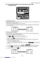
Page 41: ...e Controller RBC AMT21E UNIT No CODENo R C No Check code Indoor unit No in which an error occurred UNIT SET CL 3 1 2 Procedure 1 2 3 Description When pushing SET and buttons simultaneously for 4 seconds or more the below display appears If Service Check is displayed the mode enters in the error history mode 01 Error history order is displayed in code number window Check Code is displayed in check ...

Page 42: ...r the error history can be confirmed with the following proce dure Up to 4 error histories are stored in memory This history can be confirmed from either operating or stop 1 Push and SET buttons in succession for 4 seconds or more 2 SERVICE CHECK goes on and Item code 01 goes on 3 When selecting flash the group number if there is the alarm history the UNIT number and the latest alarm history are d...

Page 43: ...d from the indoor unit which has been used to send signals E06 is normally displayed Transmission from outdoor to indoor cannot continue for 30 seconds Multiple indoor unit address setup are duplicated In 2 remote controller control including wireless both are setup as master Header indoor unit stops and other indoor unit is operating Check item position Check remote controller inter unit wire A B...

Page 44: ...n SW09 Bit 2 on I F P C board of outdoor header unit Regular communication between indoor header and follower units There are multiple outdoor header units in 1 line There is none of outdoor header unit in 1 line Unit of other line was connected when indoor automatic address started Transmission of other outdoor unit was unavailable for 30 seconds or more Check item position Setup the address agai...

Page 45: ... or zero Open Short Resistance value of sensor is infinite or zero Open Short Check item position Note Do not set up the outdoor address manually Outdoor is performing backup Check the power of outdoor unit Is the power turned on Check connection of inter unit wire or disconnection between outdoor units Check the connector connection for communication on outdoor P C board Check outdoor P C board I...

Page 46: ...d not operate normally Outdoor P C board I F did not operate normally Inverter current detection circuit detected over current and stopped Check item position Check connection of TL sensor connector Check characteristics of TL sensor resistance value Check outdoor P C board I F error Check connection of TO sensor connector Check characteristics of TO sensor resistance value Check outdoor P C board...

Page 47: ...r due to liquid stagnation in compressor Check outdoor P C board IPDU error Check outdoor MG SW or OCR Check wiring of current detection circuit system Check outdoor P C board IPDU error Check compressor 1 case thermo circuit Connector wire P C board Check full opening of service valve Gas and liquid side Check outdoor PMV clogging PMV1 2 Check SV41 circuit leakage Check miscabling misinstallation...

Page 48: ...Check connection of TK3 sensor connector Check characteristics of TK3 sensor resistance value Check outdoor P C board I F error Check connection of TK4 sensor connector Check characteristics of TK4 sensor resistance value Check outdoor P C board I F error Check compressor 2 case thermo circuit Connector wire P C board Check full opening of service valve Gas and liquid side Check outdoor PMV cloggi...

Page 49: ...ts in a group Line address setup is duplicated against the outdoor unit in different refrigerant pipe system Indoor units with priority were duplicated Indoor units with priority were duplicated At least one indoor unit connected to a group existed in the individual indoor units Address was not yet set up Indoor unit capacity was unset On the I F P C board for service jumper line was not cut accor...

Page 50: ...ide device error 2 Check indoor P C board error n Outside device is not connected to connector CN80 1 Check indoor P C board error Check indoor I F P C board Check the lock of fan motor AC fan Check wiring Check full opening of outdoor service valves Gas side Liquid side Check clogging of outdoor PMV PMV1 2 Check characteristics of TD1 sensor resistance value Check refrigerant shortage Check 4 way...

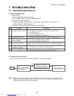
Page 51: ... voltage Check outdoor fan system error Check clogging of heat sink cooling duct Check fixation between IGBT and heat sink Check screwing and contact Check IPDU error IGBT built in temp sensor TH error Check connection of fan connector and wiring Check fan motor error Check indoor P C board error Check influence of outside air control Check indoor type code DN 10 and the capacity code DN 11 Check ...

Page 52: ...E nput power supply voltage of the fan IPDU over the setup value was detected Input power supply terminal of the fan IPDU was unconnected Power supply P C board error of the fan IPDU Check item position Check Pd pressure sensor error Check full opening of service valves Gas side Liquid side Check outdoor fan error Check outdoor fan motor error Check clogging of outdoor PMV PMV1 2 Check clogging of...

Page 53: ...ower unit error Status All stop All stop Corresponding unit only stops Error detection condition Instantaneous over current was detected when compres sor started Position was not normally detected E07 L07 L03 L08 was detected when other indoor unit in the group was defective Check item position Check connector connection and wiring on IPDU P C board Check compressor error and defect of compressor ...

Page 54: ...nected device Check P C board error of the connected device Check error input Check the check code of the unit with alarm Check the address setup Differs according to error contents of the with alarm Error detected by AI NET central control device Check code Main remote controller Outdoor 7 segment display Check code Sub code AI NET central control remote controller 97 99 b7 Detected position AI N...

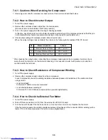
Page 55: ...0 V After checking the output when connecting the compressor lead again to the compressor terminal check surely there is no distortion on the fasten terminal lug If it is loosened caulk it with pinchers etc and then connect lead to the terminal 7 4 3 How to Check Resistance of Compressor Winding 1 Turn off the power supply 2 Remove the compressor lead cables from the compressors In each compressor...

Page 56: ...YES YES YES NO NO NO NO NO NO Is there no disconnection or connector contact error on harness out of terminal block of indoor unit Is the inter unit cable of remote controllers A B normal Is power applied to remote controller AB terminals Approx DC18V Is setup of two remote controllers without main remote controller Correct inter unit cable of remote controller Correct connector connection and che...

Page 57: ...cation from remote controller and communication adaptor This error is detected when the indoor unit cannot receive a signal from the remote controller Check communication cables of the remote controllers A and B As communication is impossible this check code E03 is not displayed on the main remote controller It is displayed on TCC LINK central controller Check code E02 Current code AI NET YES NO I...

Page 58: ...utdoor inter unit cable normal Was power turned on in order of indoor unit outdoor unit Is the end terminal resistance setup of outdoor unit normal Is power applied to fuse F03 on indoor P C board Is connection U1 U2 terminals of indoor outdoor inter unit cable normal YES Check indoor P C board Defect Replace Check connection of inter unit cable between indoor and outdoor is correct and then conne...

Page 59: ...l is not sent for a certain period from the indoor unit which has used to send signals normally E06 is displayed Is power of indoor turned on Did a power failure occur Is there no noise etc YES YES YES YES YES YES NO NO NO NO NO NO Is there no miscabling disconnection on communication line betweenindoor and outdoor Is connection of CN40 connector on indoor P C board normal Is connection of CN01 co...

Page 60: ...inter unit cable U1 U2 between indoor and outdoor short circuited Is connection of inter unit cable between indoor and outdoor correct Is there no error on power cable to outdoor unit Is F400 fuse on I F P C board opened Outdoor I F P C board failure Replace Eliminate noise Correct power cable Correct communication line I F P C board failure However an emergent operation is available by inserting ...

Page 61: ...tup of remote controllers as a master a other Remote controller address connector Check remote controller P C board Failure Replace Check code E08 96 Current code AI NET Check code name Duplicated indoor addresses Cause of operation 1 Indoor addresses are duplicated 2 Switch setup error of wall type P C board Sub code Duplicated indoor address Using a main remote controller RBC AMT21E check the se...

Page 62: ...rrect communication line Correct connection of connector Correct connection of connector Correct power cable Eliminate noise Check code E12 42 Current code AI NET Check code name Automatic address start error Cause of operation 1 When indoor automatic address started other refrigerant circuit system was setting automatic address 2 When outdoor automatic address started the indoor automatic address...

Page 63: ...door units Correct HP setup Excessive indoor units are connected Correct miscabling Perform setup of no detection for capacity over 1 Check outdoor interface P C board A ssy Check code E16 89 Current code AI NET Check code name Connected indoor units capacity over Cause of operation 1 There are 48 or more connected indoor units 2 Capacity over of total connected indoor units 3 Incorrect setup of i...

Page 64: ...r address Correct indoor address Is there any disconnection of connector or wiring from terminal block of indoor unit Are remote controller inter unit cables A B normal Are powers of all indoor units turned on Check indoor P C board Failure Replace Check power connection status of indoor unit Correct connection of connector Check circuit wire Correct remote controller inter unit wire YES NO Correc...

Page 65: ...operation 1 Misconnection of inter unit cable between indoor and outdoor 2 Outdoor I F P C board error Sub code 00 No header unit 02 Two or more header units Check code E20 42 Current code AI NET Check code name Unit connected to other line during automatic address Cause of operation When starting automatic indoor address a device in other line is connected Sub code 01 Connection of outdoor in oth...

Page 66: ...O NO Did power failure occur Is there no noise source etc Is there no miscabling or disconnection on communication line between outdoor units Is the end terminal resistance between outdoor units turned on SW30 Bit 1 Is connection of CN03 connector on outdoor I F P C board normal Check outdoor I F P C board Defect Replace Is not main power of outdoor unit turned off Check and eliminate noise etc Cl...

Page 67: ...me Duplicated follower outdoor address setup Cause of operation Addresses are duplicated by manual setup of outdoor address Do not set up outdoor address manually Check code E26 15 Current code AI NET Check code name Decrease of connected outdoor units Cause of operation 1 Outdoor unit backup setup 2 Outdoor power error 3 Communication line connection error between outdoor units 4 Connector connec...

Page 68: ... I F P C board 2 I F P C board error 3 IPDU P C board error 4 External noise Sub code 01 IPDU1 error 02 IPDU2 error 03 IPDU1 2 error 04 Fan IPDU error 05 IPDU1 fan IPDU error 06 IPDU2 fan IPDU error 07 All IPDU error or communication line error between IPDU I F P C boards or outdoor I F P C board error YES YES YES YES NO NO NO NO Replace defective IPDU P C board Correct connection of connector Rep...

Page 69: ...eplace TC2 sensor Is TCJ sensor connector CN102 Yellow on indoor P C board normally connected Are characteristics of TCJ sensor resistance value normal Check indoor main P C board Defect Replace Is TC2 sensor connector CN101 Blue on indoor P C board normally connected Are characteristics of TC2 sensor resistance value normal Check indoor main P C board Defect Replace YES YES NO NO Indoor unit temp...

Page 70: ... connection of connector TD2 sensor CN503 Pink and characteristics of sensor resistance value Refer to Outdoor unit temperature sensor characteristics If sensor is normal replace outdoor I F P C board Check code F06 18 Current code AI NET Check code name TE1 sensor error Cause of operation TE1 sensor Open Short This error code means detection of Open Short of TE1 sensor Check disconnection of circ...

Page 71: ... unit temperature sensor characteristics If sensor is normal replace outdoor I F P C board Check code name F10 0C Current code AI NET Check code name Indoor TA sensor error Cause of operation TA sensor Open Short This error code means detection of Open Short of TA sensor Check disconnection of circuit for connection of connec tor TA sensor CN104 White and characteristics of sensor resistance value...

Page 72: ...characteristics error of TE1 sensor and TL sensor 3 Outdoor P C board I F error YES YES YES NO NO NO Are installed positions of TE1 sensor and TL sensor correct Are connection of TE1 sensor connector and TL sensor connector normal Are resistance characteristics of TL sensor and TE1 sensor normal Check outdoor I F P C board Defect Replace Correct connection of connectors Correct connection of conne...

Page 73: ...or connectors correct Are output voltage characteristics of Pd sensor and Ps sensor normal Are Pd Ps output values Pd Ps during compressor operation Check outdoor I F P C board Defect Replace Value can be confirmed by 7 segment display function on outdoor I F P C board Pd SW01 02 03 1 1 2 Ps SW01 02 03 1 2 2 1 Pressure Check joint by pressure gauge 2 Pressure display on 7 segment display 3 Output ...

Page 74: ...uge 2 Pressure display on 7 segment display 3 Output voltage of I F P C board If 1 and 2 3 are different an error of pressure sensor itself is considered If 2 and 3 are different check interface P C board Connector CN500 White Correct connection of connector Check 4 way valve Check compressor Check code name F24 43 Current code AI NET Check code name Pd sensor error Cause of operation Output volta...

Page 75: ...is repeated In this case 97 error is displayed on AI NET central controller Check code name F31 1C Current code AI NET Check code name Outdoor EEPROM error Cause of operation 1 Outdoor unit power error Voltage noise etc 2 Outdoor I F P C board error Approx 3 minutes Approx 1 minute Power ON SET DATA is displayed on main remote controller SET DATA disappears LED D02 1Hz flashes for approx 10 second...

Page 76: ...e 1 Does voltage drop occur when other compressor starts Is connection of wiring or connection of connector on IPDU P C board normal Correct power line Correct connector connection or wiring Correct cause of overload Compressor error Motor burning etc Note 1 After checking the output when connecting the compressor lead again to the compressor terminal check surely there is no distortion on the Fas...

Page 77: ...r connector connection on IPDU P C board normal Is there no refrigerant stagnation in compressor shell Correct power line Correct cause of overload Compressor error Correct connector connection or wiring Correct refrigerant stagnation in compressor shell 1 380 415V 10 2 Check the following items mainly 1 Existence of abnormal sound and abnormal vibration during operation or starting 2 Abnormal ove...

Page 78: ...rror Cause of operation 1 Cabling or connector connection error on IPDU P C board 2 IPDU P C board error Sub code 01 Compressor 1 side 02 Compressor 2 side YES NO Check IPDU P C board Correct connector connection or cabling Wiring or connector connection on IPDU P C board normal FILE NO SVM 05052 ...

Page 79: ...p Never touch with hands 3 Current of compressor lead during operation or starting No rapid current change SV4 valve Connector CN311 Blue Connector CN300 301 White Is compressor normal Note 2 Repair case thermo circuit Are service valves of gas pipe and liquid pipe of outdoor unit fully opened Does not refrigerant bypass from discharge of suction through 4 way valve Refrigerant shortage clogging p...

Page 80: ...NO NO NO NO NO NO NO Open service valves fully Exchange low pressure sensor Correct SV2 and SV4 circuits Correct cabling Are SV2 and SV4 circuits normal Are service valves of gas and liquid pipe of outdoor unit fully opened Is not indoor unit with different circuit connected In cooling season go to A In heating season go to B Does indoor fan normally operate in cooling season Are characteristics o...

Page 81: ... stagnation in compressor Are characteristics of TK1 to TK4 of error detected unit normal Are balance pipe valves of all outdoor units in same line fully opened Open balance pipe valves fully reset power supply and start operation Are TK1 TK2 TK3 and TK4 sensors of the error detected unit correctly connected Is there no sensor detached or misinstallation Correct miswiring and misinstallation TK1 C...

Page 82: ... or more Set up SW02 9 and turn on SV3A SV3B SV3C valves 7 segment display Hr 3 While outdoor unit is operating check temperature change at secondary side of SV3B valve in the figure If temperature does not rise equivalent to suction temperature it is a clogging of SV3B valve Replace SV3B valve d Clogging for SV3E valve Reset the power supply ò Referring to Valve forced open close function of the ...

Page 83: ...ered in the figure 4 a Clogging check for oil equalization circuit Drive the outdoor unit Drive both compressors in the unit After driving for 10 minutes check temperature of TK1 and TK2 sensors and temperature of oil equalization circuit capillary in the figure were raised Criterion TK1 TK2 Td1 Td2 temperature Approx 10 to 30 C Oil equalization capillary tubes should be higher sufficiently than o...

Page 84: ...t stagnation in case of compressor shell Is not TK1 sensor detached Is there no miscabling or misinstallation on TK1 TK2 TK3 TK4 sensors Start a test operation in COOL or HEAT mode TK1 sensor temp is displayed on 7 segment display with SW01 02 03 1 11 2 Check TK1 sensor temp approx 10 minutes after compressor 1 has operated If low temperature continues approximately outside temp or temperature doe...

Page 85: ...inues approximately outside temp or temperature does not almost change a clogging of strainer of oil equalization circuit clogging of capillary or malfunction of check valve is considered 1 Refer to item H07 error 2 If OCR operates even after manual reset of OCR check whether the wiring to the current sensor TO2 of Comp IPDU is correct or not Outdoor unit temp sensor characteristics 4 Correct misc...

Page 86: ...03 1 13 2 Check TK3 sensor temp approx 10 minutes after compressor 2 has operated If low temperature continues approximately outside temp or temperature does not almost change a clogging of parallel capillary is considered Note 1 Refer to item H07 error Outdoor unit temp sensor characteristics 4 Correct miscabling misinstallation TK1 CN514 TK2 CN515 TK3 CN516 TK4 CN523 YES YES YES NO NO NO Check I...

Page 87: ...here no miscabling or misinstallation on TK1 TK2 TK3 TK4 sensors Check the clogging of SV3E valve 1 Refer to item H07 error 2 If OCR operates even after manual reset of OCR check whether the wiring to the current sensor TO2 of Comp IPDU is correct or not Correct miscabling misinstallation TK1 CN514 TK2 CN515 TK3 CN516 TK4 CN523 YES YES YES NO NO NO Replace SV3E valve Correct installation of sensor...

Page 88: ...ddress Cause of operation Outdoor line addresses are duplicated Check code name L05 96 Current code AI NET Check code name Duplicated indoor units with priority Displayed on indoor unit with priority Cause of operation 1 Two or more prior indoor units exist This check code is displayed on the set indoor unit when setup of indoor unit with priority is duplicated Priority setup with two or more unit...

Page 89: ...played on the unit other than the setup indoor unit and outdoor unit As only one indoor unit with priority is valid change the setup Check code name L07 99 Current code AI NET Check code name Group line in individual indoor unit Cause of operation The group line is connected in the individual indoor unit Is there group cabling Check indoor P C board Failure Replace There is individual indoor unit ...

Page 90: ...ed on at the first time after installation Because the address is not yet set up Turn on the power of indoor units Turn on the power of outdoor unit again Are powers of all the indoor units turned on Disconnect connectors between U1 U2 and U3 U4 Clear addresses Refer to Address clear Re execute address setup Refer to Address setup YES NO Set up capacity data of indoor unit Setup item code DN 11 Ch...

Page 91: ... Central control addresses are duplicated Check code name L28 46 Current code AI NET Check code name Quantity over of connected outdoor units Cause of operation 1 Quantity over of connected outdoor units 2 Connection error of communication line between outdoor units 3 Outdoor I F P C board error Are not two or more central control system identical network addresses connected Check the network adap...

Page 92: ... trouble Correct connection of connector Replace communication line I F P C board error I F P C board error Correct connection of connector Is there voltage fluctuation between 4 and 5 pins of CN600 on I F P C board Measurement by tester DC0 to 5V 5 pin GND Is there voltage fluctuation between 3 and 5 pins of CN600 on I F P C board Measurement by tester DC0 to 5V 5 pin GND Is jumper setup of outdo...

Page 93: ...operation 1 Outdoor unit power error 2 Outdoor I F P C board error Does outside device correctly operate Check cause of the operation Is outside device connected to connector CN80 Check indoor P C board Failure Replace Check outside device Failure Replace YES YES NO NO Check outdoor I F P C board Is there any trouble of outdoor unit power supply Check power voltage and line Check auxiliaty noise e...

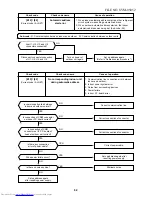
Page 94: ...l or replace SV41 valve Are characteristics of TD1 sensor resistance normal Are service valve of gas and liquid sides fully opened Are not indoor units of different refrigerant circuit connected Refrigerant shortage clogging pipe breakage Connector CN300 301 White Refer to Outdoor unit temperature sensor characteristics 4 Check there is no pipe breakage and then recharge the refrigerant Check with...

Page 95: ...SW operate Are parts of high pressure SW normal Is service valve fully opened B Cooling operation Is SV2 circuit normal Open service valve fully Replace the high pressure sensor Repair faulty parts Eliminate the interfered causes Repair SV2 circuit Is circuit cabling normal Check and correct cabling Does cooling outdoor fan normally operate Is there no crack or coming off of fan Are characteristic...

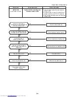
Page 96: ...etc Are not indoor units of different refrigerant circuit connected Is there clogging of valve Is indoor PMV normal Does heating indoor fan normally operate Repair faulty parts A C Repair faulty position Connector connection cabling coil installation clogging etc Refrigerant overcharge clogging pipe breakage abnormal overload condition Check and correct the cabling Check with miscabling check func...

Page 97: ...Power voltage error 2 Outdoor fan system error 3 Heat sink installation error 4 Clogging of hear sink cooling duct 5 IPDU P C board error TH sensor error Sub code 01 Compressor 1 side 02 Compressor 2 side Correct wiring such as cable to compressor or connector connection Is power voltage normal Is indoor fan normal Check IPDU P C board Is wiring of IPDU normal Is screw between IPDU and heat sink l...

Page 98: ...210 when turning on the motor except heating mode from remote controller Check it within 15 seconds after start of operation Does voltage 0 to 15V No of rotation return signal generate between 6 and 3 of motor connector CN210 when rotating cross flow fan with hands under condition of operation stop Start cooling operation with LOW setup Change setup of cooling wind to HIGH Replace indoor fan motor...

Page 99: ...all units Replace check valve of main discharge pipe Correct connector connection CV2 CN302 Correct connector connection CN300 CN301 YES YES YES YES YES YES YES YES NO NO NO NO NO NO NO NO Check code name P13 47 Current code AI NET Check code name Outdoor liquid back detection error Cause of operation 1 PMV1 PMV2 error 2 Pd sensor Ps sensor error 3 Clogging of SV2 circuit 4 Clogging of SV3B circui...

Page 100: ...ts Are service valves at gas and liquid side fully opened Are characteristics of TS1 sensor resistance normal Is there no leakage of SV41 and 42 valve circuits Refrigerant shortage clogging pipe breakage Connectors CN300 301 White Refer to outdoor temp sensor characteristics 2 Check there is no clogging and pipe breakage and then recharge refrigerant Coil valve body disconnection of cable etc Is o...

Page 101: ...cabling Are service valves of gas and liquid sides fully opened Are characteristics of TD1 TD2 sensor resistance normal Is SV4 valve circuit normal Coil misinstallation valve leakage Are not indoor units in different refrigerant circuit connected Refrigerant shortage clogging pipe breakage Connectors CN300 301 White Refer to outdoor temp sensor characteristics 4 Check with miscabling check functio...

Page 102: ...rigerant shortage clogging pipe breakage Connectors CN300 301 White Refer to outdoor unit temperature sensor characteristics 4 Check there is no pipe breakage and then recharge refrigerant Is outdoor PMV normal 1 Connector connection 2 Cabling 3 Coil 4 Valve body 5 Outdoor I F P C board SV4 circuit 1 Are not SV41 and SV42 valve coils installed reversely 2 Is there no leakage through SV42 circuit Y...

Page 103: ...ance value of TS1 and TE1 sensors normal Are output voltage characteristics of Pd and Ps sensors normal Are connection and installation of TE1 and TL sensors correct Reset the power supply and start heating test operation Correct connector connection 4 way valve coil CN317 Correct connection and installation 1 Check TS and TE temperature of the outdoor unit which compressors is operated I F SW01 1...

Page 104: ...age abnormal overload condition Are characteristics of high pressure sensor normal Open service valves fully Check parts Failure Replace 1 Pressure by pressure gauge Check joint 2 Pressure display on 7 segment display 3 Output voltage of I F P C board If 1 and 2 3 are different an error of pressure sensor is considered If 2 and 3 are different check I F P C board Is there a cause to interfere oper...

Page 105: ... sensor TC2 and TCJ resistance normal Is connector connection coil normal Does heating indoor fan normally operate Is check valve of main discharge pipe normal Are not indoor units of different refrigerant circuit connected Check indoor P C board Faulty Replace C Is there a cause to interfere operation of heat exchanger of indoor unit 1 Air filter clogging 2 Heat exchanger clogging 3 Air short cir...

Page 106: ...sor error Heat sink overheat D TH sensor error E Vdc error Is not outdoor fan motor locked Is sub code of outdoor I F P C board 0d Check fan IPDU Correct cable connector connection Correct cause of overload Retightening of screws etc Replace fan IPDU Is there no problem such as stuffing or blast blowing to discharge port of outdoor fan Are cable connector connection on fan IPDU and power P C board...

Page 107: ... 1 side 02 Compressor 2 side Is power voltage of outdoor unit normal Is there no fusing of AC30A fuse Replace IPDU P C board Is compressor normal Is wire connector connection on IPDU P C board normal Is smoothing condenser normal 1500µF 350V Correct power line Replace compressor Correct connection of wire connector Check capacity coming out external appearance Replace fuse and IPDU P C board YES Y...

Page 108: ... in the group is abnormal When the header unit of the group detected E03 L03 L07 L08 error the follower unit of the group displays P31 error and stops There are no check code display and alarm record of the main remote controller Is not grounded Is not winding opened Are connector connection and wiring normal Is not winding shorted Is winding resistance 0 6 to 1 2W Check IPDU P C board Failure Rep...

Page 109: ...upply Clear check code Eliminate noise etc Check power transformer of the network adaptor P C board MCC 1401 Failure Replace Check central controller Failure Replace Check indoor P C board Failure Replace Did a block out occur Is there no noise etc Does the network adaptor P C board LED D01 turn on Is there no connection error of power line Is not main power supply turned on Are AI NET X and Y com...

Page 110: ... 40 50 Characteristic 1 Temperature C Indoor TA sensor Resistance k W 50 0 100 150 200 5 0 10 15 20 20 30 10 0 10 20 30 40 50 60 70 80 90 100 Characteristic 2 Temperature C Indoor TC1 TC2 TCJ sensors Resistance k W 10 C or lower Resistance k W 10 C or higher FILE NO SVM 05052 ...

Page 111: ... unit 1 2 3 Outdoor unit Indoor unit 1 Central control remote controller Option 1 U3 U4 Sensor display P C board MCC 819 Main P C board MCC 1510 DC20V DC12V DC5V DC280V Sensor part Louver motor Indoor fan motor EEPROM TA sensor TC sensor TCJ sensor HA Outdoor unit AC synchronous signal input circuit Serial send receive circuit Remote controller A B setup Fan motor control circuit Start Alarm Ready...

Page 112: ...3 U4 Sensor display P C board MCC 819 Main P C board MCC 1510 DC20V DC12V DC5V DC280V Sensor part Louver motor Indoor fan motor EEPROM TA sensor TC sensor TCJ sensor HA Outdoor unit AC synchronous signal input circuit Serial send receive circuit Remote controller A B setup Fan motor control circuit Start Alarm Ready Thermostat ON COOL HEAT FAN Outside output Power circuit Max 8 units are connectab...

Page 113: ...der of hear exchanger Pay attention to mounting positions of each sensor when reassembling of electric parts Be sure to apply marking etc to TC2 and TCJ sensors before removing because their shapes are reassembled 5 Take off LED base fixing screw 1 pc and remove LED base 6 Remove terminal block cover and then remove fan motor connector 5P louver motor connector 5P and PMV motor connector 6P from m...

Page 114: ...box 4 Take off bundling band of PMV motor lead wires 5 Using a spanner remove PMV motor Caution in reassembling Draw out lead wires of PMV motor from positions same to original positions before removing Remarks T Horizontal grille 1 Remove shaft of the horizontal grille from the rear plate First remove the left shaft and then remove the other shafts while sliding the horizontal grille leftward Scr...

Page 115: ...nger 4 Take off fixing screws 2 pcs at the right side of the heat exchanger Remarks V Bearing base Bearing Drain pipe Bearing 1 Perform works of items Q X 4 and X 5 and then remove bearing from the bearing base Caution to reassembly In case of shooting out of bearing part from the housing push into the specified position and incorporate in the main unit Pipe holder Fixing screws Fixing screws FILE...

Page 116: ...from the discharge port 4 Take off fixing screws 2 pcs to remove the motor band Right 5 Pull out the fan motor outward Remarks Assemble the fan motor as shown below X 1 Perform works of items R and T 2 Take off fixing screws 2 pcs at the left side of the end plate of the heat exchanger and then take off fixing screws 2 pcs of the bearing base 3 Make the left side of the heat exchanger float slight...

Page 117: ...ion in the following figure and then mount the fan motor Mount the cross flow fan so that the right end of joint which is first one from right of the cross flow fan is set at position 70 5mm apart from wall of the rear side of the main unit Mount the cross flow fan so that D cut part at the center comes to the mounting hole of set screw Determine the position of fan motor as shown in the figure fo...

Page 118: ...ee H2 in Page 119 120 ò Write the read data to EEPROM see H3 in Page 121 ò Power reset If in group operation reset the power for all indoor units which are connected to the remote controller CASE 2 Before replacement the setup data can not be read out by the wired remote controller Replace service P C board power ON see H2 in Page 119 120 ò Write the data such as option input selection setup to EE...

Page 119: ...the fan H2 Replacement of service P C board 1 Replace the P C board with a service P C board In this time setting of jumper line cut or setting of DIP switch on the former P C board should be reflected on the service P C board Refer to the following table about DIP switch setting and drawing of P C board parts layout 2 It is necessary to set Indoor unit to be exchanged Remote controller 1 1 Based ...

Page 120: ...Custom Multi model selection No use MMK AP 2H series 1 1 ON OFF At shipment OFF Without terminator OFF A selection ON Multi model OFF 1 Match to set up contents of P C board before replacement A B A B A B Indoor unit P C board Remote controller Group wire Group wire Case 1 Remove the group wire of the terminal blocks A and B of the changed indoor unit and then install the remote controller only Re...

Page 121: ...e procedure 1 5 Using the set temperature buttons set to the item code DN 2 Setup of lighting time of filter sign 6 The contents of the displayed setup data in this time should be agreed with the contents in the previous memorandum in H1 1 If data disagree change the displayed setup data to that in the previous memorandum by the timer time buttons and then push SET button OK when the display goes ...

Page 122: ...o output selection T10 Input selection T10 Sensor selection Timer set Wired remote controller Flap selection of cooling Memo Be sure to set as 0008 At shipment 0001 150 hour 0000 Standard 0099 Unfixed 0002 2 C 0000 Standard 0001 No auto mode Automatic selection by cooling heating connected outdoor unit 0000 Heat pump 0008 High wall type According to capacity type 0099 Unfixed 0099 Unfixed 0099 Unf...

Page 123: ...n No 218 43T19321 Holder sensor 219 43T49317 Rubber Seal Evaporator 220 43T49006 Holder for Plate 221 43T22002 ASM M Bearing 222 43T39314 Base Bearing Ass y 223 43T20302 Fan Cross Flow 224 43T21344 Fan Motor MF 340 30 1 225 43T39315 Band Motor Left 226 43T39303 Band Motor Right 227 43T82301 Plate Installation 228 43T69309 Wireless Remote Controller WH H2UE 229 43T83003 Holder Remote Controller 230...

Page 124: ...Block 3P 15A 250V 403 43T60362 Terminal 405 43T50303 Temperature sensor 407 43T69428 P C Board Location Part Description No 408 43T69429 Display Unit 409 43T62003 Cord Clamp 410 43T61301 Cover Parts E 411 43T62315 Cover Connect P 412 43T72307 Drain Guide 404 43T50312 Sensor Heat Exchanger 406 43T50313 Sensor Thermostat FILE NO SVM 05052 404 405 ...

Page 125: ...TOSHIBA CARRIER CORPORATION ...

Reviews: