6. CONFIGURATION OF CONTROL CIRCUIT
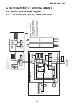
6-1. Indoor Controller Block Diagram
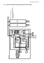
6-1-1. Case of Main (Sub) Remote Controller Connected
Displa
y
par
t
LCD
Displa
y
LCD
Function setup
CPU
Remote controller
comm
unication
circuit
Remote controller
comm
unication
circuit
CPU
R78/G13
Dr
iv
er
Dr
iv
er
Displa
y
par
t
LED
K
e
y s
witch
Po
w
e
r
circuit
DC5V
LCD
dr
iv
er
Function setup
CPU
K
e
y s
witch
Po
w
e
r
circuit
Secondar
y
batter
y
DC5V
*
2
Same
as left
CN2
CN1
A
B
1
23
L
N
U1
U2
U1
U2
A
B
Same
as left
A
B
Outdoor
unit
1
23
Outdoor
unit
Indoor unit
#1
Sensor display P
.C.
board
(
WP-033
)
Main P
.C.
board (MCC-
1696
)
DC20V
DC12V
DC5V
DC280V
Sensor par
t
Louv
er
motor
Indoor
fan motor
EEPR
OM
T
A sensor
TC
1
sensor
TCJ sensor
HA
P
o
w
er supply
1Ø, 220 - 240V
, 50Hz
1Ø, 220V
, 60Hz
Outdoor unit
AC
synchronous
signal input
circuit
BU
S
comm
unication
circuit
Remote
controller
A/B setup
F
an motor
control circuit
Star
t
Alar
m
Ready
Ther
mostat ON
COOL
HEA
T
F
AN
Outside
output
Po
w
e
r
circuit
Max.
8 units are connectab
le
.
*1
In g
roup connection, mount the
centr
al control remote controller to
g
roup header unit.
*2
Connection of w
eekly timer to sub
remote controller is una
v
ailab
le
.
Wired (Simple)
master remote contr
oller
(Up to 2 sets)
Central remote contr
oller
LED
TC
2
sensor
FILE NO. SVM-17045
- 24 -
FILE NO. SVM-17045
- 24 -


