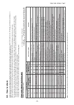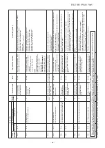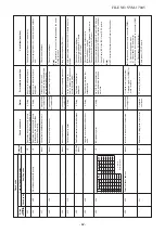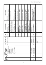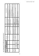
8-4.
Check
Code
and
Check
Position
Displayed
on
the
Remote
Controller
and
Outdoor
Unit
(7-Segment
Display
of
Interface)
<In
case
of
SUPER
MODULAR
MU
LTI
SYSTEM>
Chec
k code
Wired remote
contr
oller
E01
E02
E03
E04
E06
—
E08
E09
E10
E12
Outdoor 7-segment displa
y
Chec
k code
A
uxiliar
y
code
——
——
——
——
E06
No
. of indoor units
which receiv
ed
signal nor
mally
E07
—
E08
Duplicated indoor addresses
——
——
E12
01
:
Indoor/outdoor comm
unication
02
:
Between outdoors comm
unication
Detected position
Remote controller
Remote controller
Indoor
unit
Indoor
unit
I/F
I/F
Indoor
I/F
Remote controller
Indoor
unit
I/F
Chec
k code name
Comm
unication error betw
een
indoor and remote controller
(Detected at remote controller side)
Remote controller sending error
Comm
unication error betw
een
indoor and remote controller (Detected at indoor side)
Indoor/outdoor comm
unication
circuit error (Detected at indoor side)
Decreased number of indoor units
Indoor/outdoor comm
unication
circuit error (Detected at outdoor side)
Duplicated indoor addresses
Duplicated master remote controllers
Comm
unication error betw
een
indoor P
.C
. board assemb
ly
A
utomatic address star
t error
Status
Corresponding unit only stops
.
Corresponding unit only stops
.
Corresponding unit only stops
.
Corresponding unit only stops
.
All stop
All stop
All stop
Corresponding unit only stops
.
Corresponding unit only stops
.
All stop
E
rr
or detection condition
Comm
unication interr
upted betw
een indoor
P.
C
. board and remote controller
.
Signal could not be sent from remote controller to indoor unit.
No comm
unication from remote controller
(including wireless) and comm
unication
adapter
.
Indoor unit does not receiv
e comm
unication
from outdoor unit.
When signal is not sent f
or a cer
tain per
iod
from the indoor unit which has been used to send signals
.
Tr
ansmission from outdoor to indoor cannot
continue f
or 30 seconds
.
Multiple indoor unit address setup are duplicated.
In 2-remote controller control (including wireless), both are setup as master (Header indoor unit stops and other indoor unit is oper
ating.)
Comm
unication w
as not succeeded after
po
wer w
as supplied or dur
ing
comm
unication.
•
When indoor automatic address star
ted,
other refr
iger
ant circuit system w
as setting
automatic address
.
•
When outdoor automatic address star
ted,
indoor automatic address w
as e
xecuted.
Chec
k item (position)
•
Chec
k remote controller inter-unit cab
le (A/B).
•
Chec
k disconnection, connector contact error
.
•
Chec
k indoor po
wer supply
.
•
Chec
k indoor P
.C
. board error
.
•
Chec
k remote controller address setup
.
(When two remote controllers operate)
•
Chec
k remote controller P
.C
. board.
•
Chec
k the comm
unication wire of remote controller
:
Exchange remote controller
.
•
Chec
k remote controller and comm
unication adapter wir
ing.
•
Chec
k po
w
er-ON order of indoor/outdoor
.
•
Chec
k indoor address setup
.
•
Chec
k inter-unit cab
ling between indoor and outdoor
.
•
Chec
k outdoor end ter
minal resistance setup (SW30-2).
•
Chec
k the po
w
er supply of indoor unit.
(P
ow
er-ON)
•
Chec
k connection of communication line betw
een indoor and outdoor
.
•
Chec
k connector connection f
or comm
unication in indoor P
.C
. board.
•
Chec
k connector connection f
or comm
unication in outdoor P
.C
. board.
•
Chec
k indoor P
.C
. board f
ailure
.
•
Chec
k outdoor P
.C
. board (I/F) f
ailure
.
•
Chec
k outdoor ter
minator resistor setup (SW30-2).
•
Chec
k the communication connection betw
een indoor and outdoor
.
•
Chec
k indoor address
.
•
Chec
k the change of remote controller connection (Group / individual)
after setup of indoor address
.
•
Chec
k remote controller setup
.
•
Chec
k remote controller P
.C
. board.
•
Indoor P
.C
. board f
ailure
•
Setup the address again after disconnecting comm
unication
connection with other refr
igerant circuit system.
FILE NO. SVM-17045
- 56 -

