– 21 –
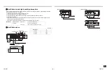
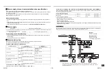
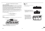
<In the case of combining with outdoor units other than Super Modular Multi System u series (SMMS-u)>
• The length of the communication line (L1+L2+L3) means the total length of the inter-unit wire length between
indoor and outdoor units added with the central control system wire length.
REQUIREMENT
For connection of between indoor and outdoor units line / between outdoor and outdoor units line or central control
line, wire each line using wires with the same type and size. If different wire types and size are mixed and used in a
system, communication trouble is caused.
Control wiring between indoor units, and outdoor unit
(L2, L3)
(2-core shield wire, non-polarity)
Wire size :
1.25 mm
2
2.0 mm
2
(Up to 1000m)
(Up to 2000m)
Central control line wiring
(L1)
(2-core shield wire, non-polarity)
Control wiring between outdoor units
(L4)
(2-core shield wire, non-polarity)
Wire size :
1.25 to 2.0 mm
2
(Up to 100m)
U2
U4
U3
U4
U3 U4
Uh
U6
U4
U1 U2
A
B
U6
U4
U1 U2
A
B
U6
U4
U1 U2
A
B
U6
U4
U1 U2
A
B
U1
U3
U2
U5 U6
U3 U4
U1
U2
U5 U6
U3 U4
U1
U2
U5 U6
U3 U4
U1
Uv
Uv
Uv
Uv
[Communication line]
(L1 + L2 + L3)
= Up to 2000m
L4
= Up to 100m
Central control device
Outdoor unit
Indoor unit
Remote controller
<Other than U series>
<U series>*
<U series>*
(SMMS-i)
(SMMS-e)
(MiNi SMMS)
etc.
<U series>*
*Even if the indoor units, the remote controllers, and the central control device are models
other than U series, their system diagrams for the wiring specifications are the same as the
system diagram above.
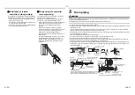
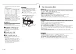
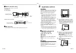
Remote controller wiring
• 2-core with non-polarity wire is used for the remote controller wiring and group remote controllers wiring.
CAUTION
CAUTION
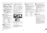
• The remote controller wire (Communication line) and AC 208-240V wires cannot be parallel to contact
each other and cannot be stored in the same conduits. If doing so, a trouble may be caused on the control
system due to noise or other factor.
• If U series models (TU2C-Link) are combined with models other than U series (TCC-Link), the wiring
specifications and maximum number of connectable indoor units will be changed. Pay attentions to their
communication specifications when carrying out the installation, maintenance, or repair. For its details, refer to the
“Communication line” in
8 Electrical connection
.
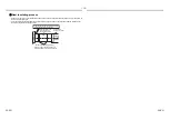
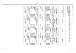
Max. number of connectable indoor units, and communication type
∗
Other than U series
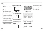
REQUIREMENT
After carrying out installation of additional indoor unit, relocation, or repairing, set the addresses again.
For its detail, refer to the Installation Manual attached to the outdoor unit.
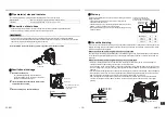
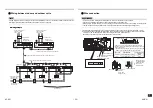
Remote controller wiring, remote controller inter-unit
wiring
86 remote controller
Wire size:0.5 mm
2
to 1.5 mm
2
Other than 86 remote controller
Wire size:0.5 mm
2
to 2.0 mm
2
Total wire length of remote controller wiring and
remote controller inter-unit wiring = L + L1 + L2 +...
Ln
In case of one remote controller
Up to 500 m
In case of two remote controller
Up to 400 m
Max. length of each remote control wiring between indoor units = L1, L2, ..., Ln
Up to 200 m
Unit type
Outdoor unit
U series
U series
U series
U series
∗
∗
∗
∗
Indoor unit
U series
U series
∗
∗
U series
U series
∗
∗
Remote controller
Remote sensor
U series
∗
U series
∗
U series
∗
U series
∗
Communication type
TU2C-Link
TCC-Link
Max. number of connectable
units
16
8
L1
L
n
L
2
L
Indoor unit
Indoor unit
Indoor unit
Remote controller inter-unit wiring
Indoor unit
Remote
controller
For number of max. connectable units,
refer to the following table.
Remote
controller
wiring
41-EN
42-EN


