background image

– 13 –

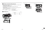
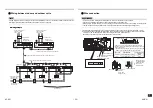
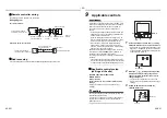
Heat insulating process

• As shown in the figure, cover the flexible hose and hose band with the attached heat insulator up to the bottom of 

the indoor unit without gap.

• Cover the drain pipe seamlessly with a heat insulator locally procured so that it overlaps with the attached heat 

insulator of the drain connecting section.

Ind

oor un

it

Banding band (Locally procured)

Wrap the attached heat insulator seamlessly 
from the surface of the indoor unit.

Heat insulator of the 

drain connecting 

section (Accessory)

Heat insulator 
(Locally procured)

* Direct the slits and seams of the heat 

insulator upward to avoid water leakage.

25-EN

26-EN

Summary of Contents for MMD-UP0031SPHY-E

Page 1: ...CONDITIONER MULTI TYPE Installation Manual Indoor Unit Model name Slim Duct Type MMD UP0031SPHY E MMD UP0051SPHY E MMD UP0071SPHY E MMD UP0091SPHY E MMD UP0121SPHY E MMD UP0151SPHY E MMD UP0181SPHY E MMD UP0241SPHY E MMD UP0271SPHY E ...

Page 2: ...ve been trained and is thus thoroughly acquainted with the knowledge related to this work The qualified installer who is allowed to do the refrigerant handling and piping work involved in installation relocation and removal has the qualifications pertaining to this refrigerant handling and piping work as stipulated by the local laws and regulations and he or she is a person who has been trained in...

Page 3: ...manner indicates that failure to adhere to the directions in the caution could result in slight injury 2 or damage 3 to property if the product is handled improperly 1 Serious bodily harm indicates loss of eyesight injury burns electric shock bone fracture poisoning and other injuries which leave aftereffect and require hospitalization or long term treatment as an outpatient 2 Slight injury indica...

Page 4: ...1 is allowed to undertake work at heights using a stand of 50 cm or more or to remove the intake grille of the indoor unit to undertake work Wear protective gloves and safety work clothing during installation servicing and removal Do not touch the aluminum fin of the unit You may injure yourself if you do so If the fin must be touched for some reason first put on protective gloves and safety work ...

Page 5: ...itioner is not installed appropriately a unit may topple over or fall down causing an accident If refrigerant gas has leaked during the installation work ventilate the room immediately If the leaked refrigerant gas comes in contact with fire noxious gas may generate Use forklift truck to carry in the air conditioner units and use winch or hoist at installation of them Helmet must be worn to protec...

Page 6: ...r connecting wire must be connected in the middle Connection using a solderless terminal etc Connection trouble in the places where the wire is connected in the middle may give rise to smoking and or a fire Electrical wiring work shall be conducted according to law and regulation in the community and installation manual Failure to do so may result in electrocution or short circuit Test run Before ...

Page 7: ...ulting in rupture injury or other trouble 1 Refer to the Definition of qualified installer or qualified service person CAUTION CAUTION R410A refrigerant air conditioner installation This air conditioner adopts the HFC refrigerant R410A which does not destroy ozone layer The characteristics of R410A refrigerant are easy to absorb water oxidizing membrane or oil and its pressure is approx 1 6 times ...

Page 8: ... used Blocked filters may cause the air conditioner s performance to deteriorate condensation to form the plastic parts to be damaged and other such problems to result Places where iron or other metal dust is present If iron or other metal dust adheres to or collects on the interior of the air conditioner it may spontaneously combust and start a fire Locations near obstructions such as ventilation...

Page 9: ...he high humidity atmosphere Apply also a sufficient heat insulation to the duct and connecting part of the duct Installation space Unit mm Reference Condensation test conditions Indoor side 27 C dry bulb temperature 24 C wet bulb temperature Air volume Low air volume operation time 4 hours A 235 or more Air outlet Refrigerant piping 5 or more Drain piping 210 450 Ceiling 100 100 or more 2500 or mo...

Page 10: ...l the setting direction Carry the package by two or more persons and do not bundle it with plastic band at positions other than specified To install vibration isolation material to hanging bolts confirm that it does not increase the unit vibration External dimensions 37 80 113 100 80 16 56 388 320 260 85 110 155 300 35 173 22 40 164 40 23 210 Hanging bolt pitch A For air intake Unit external dimen...

Page 11: ...the hanging bracket of the indoor unit to hang down the indoor unit Check that four sides are horizontal with a level gauge Horizontal degree Within 5 mm Hanging bolt M10 or W3 8 4 pieces Nut M10 or W3 8 12 pieces Washer M10 8 pieces New concrete slab Install the bolts with insert brackets or anchor bolts Steel frame structure Use existing angles or install new support angles Existing concrete sla...

Page 12: ...ion Improper heat insulation will cause condensation to form The drain pipe must be sloping downward at an angle of 1 100 or more and do not run the pipe up and down arched shape or allow it to form traps Doing so may cause abnormal sounds Restrict the length of the traversing drain pipe to 20 meters or less For a long pipe provide support brackets at intervals of 1 5 to 2 meters to prevent flappi...

Page 13: ...k that water drain is properly performed and water does not leak from the connecting part of the pipes When doing this also check that no abnormal sounds are heard from the drain pump motor Check draining also when installed in heating period When the electrical and wiring work has been completed Pour some water by following the method shown in the following figure Then while performing a cooling ...

Page 14: ... insulator locally procured so that it overlaps with the attached heat insulator of the drain connecting section Indoor unit Banding band Locally procured Wrap the attached heat insulator seamlessly from the surface of the indoor unit Heat insulator of the drain connecting section Accessory Heat insulator Locally procured Direct the slits and seams of the heat insulator upward to avoid water leaka...

Page 15: ... the following dimensions manufacture duct at the local site Some models have no drain guard here UP003 UP005 UP007 UP009 UP012 UP024 UP027 Under air intake Under air intake Back air intake Back air intake UP015 UP018 Under air intake Back air intake Unit mm ...

Page 16: ...Pa High 20Pa High 30Pa Low 30Pa High 10Pa Low 10Pa Lower limit of external static pressure 50Pa Low 50Pa High 40Pa Low 40Pa Low 20Pa High 20Pa High 30Pa Low 30Pa High 10Pa Low 10Pa Lower limit of external static pressure 50Pa Upper limit of external static pressure 50Pa High 50Pa Lower limit of external static pressure 50Pa Upper limit of external static pressure 50Pa Air Flow m3 h Air Flow m3 h A...

Page 17: ...of external static pressure 50Pa Upper limit of external static pressure 50Pa Air Flow m3 h Air Flow m3 h Air Flow m3 h Air Flow m3 h Static Pressure Pa Static Pressure Pa Standard air volume 690 m3 h Standard air volume 780 m3 h Standard air volume 1080 m3 h Standard air volume 1140 m3 h Static Pressure Pa Static Pressure Pa Lower limit of external static pressure 50Pa Upper limit of external sta...

Page 18: ... into the square hole Square hole Back air intake Filter rail 2 Screw Accessory 4 Filter rail 2 Screw Accessory 4 Filter stopper Accessory Insert the filter into the rail in the direction of the arrow as shown in the figure below until it reaches the filter stopper Installation location of filter rail Under air intake Back air intake 㽲 㽳 㽴 㽵 㽲 㽳 㽴 㽵 Under air intake Back air intake 33 EN 34 EN Mod...

Page 19: ...Remove burrs completely Remaining burrs may cause gas leakage 2 Insert a flare nut into the pipe and flare the pipe Use the flare nut provided with the unit or the one used for the R410A refrigerant The flaring dimensions for R410A are different from the ones used for the conventional R22 refrigerant A new flare tool manufactured for use with the R410A refrigerant is recommended but the convention...

Page 20: ...specified wires for wiring connection to the terminals Securely fix them to prevent external forces applied to the terminals from affecting the terminals Incomplete connection or fixation may cause a fire or other trouble Connect earth wire grounding work Incomplete earthing cause an electric shock Do not connect earth wires to gas pipes water pipes lightning conductor or telephone earth wires App...

Page 21: ...ies model Other than U series MMY MAP MCY MHP Indoor unit MM UP This letter indicates U series model Other than U series MM AP Wired remote controller RBC A U This letter indicates U series model Other than U series Wireless remote controller kit receiver unit RBC AXU This letter indicates U series model Other than U series Remote sensor TCB TC U This letter indicates U series model Other than U s...

Page 22: ...N The remote controller wire Communication line and AC 208 240V wires cannot be parallel to contact each other and cannot be stored in the same conduits If doing so a trouble may be caused on the control system due to noise or other factor If U series models TU2C Link are combined with models other than U series TCC Link the wiring specifications and maximum number of connectable indoor units will...

Page 23: ...minal numbers Incorrect connection causes a trouble Pass the wires through the bushing of wire connection holes of the indoor unit Keep a margin Approx 100 mm on a wire to hang down the electrical control box at servicing or other purpose The low voltage circuit is provided for the remote controller Do not connect the high voltage circuit 1 Before performing wiring work in the electrical control b...

Page 24: ...power has been turned on Before the air conditioner was shipped from the factory all units are set to STANDARD factory default If necessary change the indoor unit settings The settings are changed by operating the wired remote controller The settings cannot be changed using only a wireless remote controller and simple remote controller by itself so install a wired remote controller separately as w...

Page 25: ... External static pressure 0000 10Pa Standard Factory default 0001 20Pa High static pressure 1 0003 30Pa High static pressure 2 0004 40Pa High static pressure 3 0006 50Pa High static pressure 4 SW501 1 OFF ON OFF ON SW501 2 OFF OFF ON ON Set data 0000 Factory default 0001 0003 0006 SW501 1 MCU IC501 SW501 2 To secure better effect of heating When it is difficult to obtain satisfactory heating due t...

Page 26: ...h setting button Do not run the air conditioner in a mode other than Cool or Heat The temperature setting function does not work during test run The check code is displayed as usual 4 After the test run push OFF timer button to stop a test run TEST disappears on the display and the air conditioner enters the normal stop mode 4 3 1 2 3 Wired remote controller 1 Turn on the power of the air conditio...

Page 27: ...leaning maintenance work Such maintenance can extend the life of the product though it involves the owner s expense Failure to clean the indoor and outdoor units regularly will result in poor performance freezing water leakage and even compressor failure Inspection before maintenance Following inspection must be carried out by a qualified installer or qualified service person Maintenance List Part...

Page 28: ...ure indicator The OFF timer indicator alternately shows the check code and the indoor Unit No in which the problem occurred 2 Each time the setting button is pushed the recorded troubleshooting history is displayed in sequence The troubleshooting history appears in order from 01 newest to 04 oldest CAUTION CAUTION In the troubleshooting history mode DO NOT push the Menu button for over 10 seconds ...

Page 29: ...Communication trouble between indoor unit and remote controller Detected at indoor unit side Indoor unit E04 Communication circuit trouble between indoor outdoor unit Detected at indoor unit side Indoor unit E06 E06 No of indoor units in which sensor has been normally received Decrease of No of indoor units I F E07 Communication circuit trouble between indoor outdoor unit Detected at outdoor unit ...

Page 30: ...or ALT TS1 or TS3 sensor trouble I F F13 F13 01 Comp 1 side 1d Comp 1 side 02 Comp 2 side 2d Comp 2 side 03 Comp 3 side ALT TH sensor trouble Compressor inverter F15 F15 ALT Outdoor unit temp sensor miswiring TE TL I F F16 F16 ALT Outdoor unit pressure sensor miswiring Pd Ps I F F22 F22 ALT TD3 sensor trouble I F F23 F23 ALT Ps sensor trouble I F F24 F24 ALT Pd sensor trouble I F F29 SIM Indoor un...

Page 31: ... Outdoor unit line address duplicated I F L05 SIM Duplicated indoor units with priority Displayed in indoor unit with priority I F L06 L06 No of indoor units with priority SIM Duplicated indoor units with priority Displayed in unit other than indoor unit with priority I F L07 SIM Group line in individual indoor unit Indoor unit L08 L08 SIM Indoor unit group Address unset Indoor unit I F L09 SIM In...

Page 32: ...as leak detection I F P17 P17 ALT Discharge temp TD2 trouble I F P19 P19 Detected outdoor unit number ALT 4 way valve inverse trouble I F P20 P20 ALT High pressure protective operation I F P22 P22 0 Element short circuit E Vdc voltage trouble 1 Position detection circuit trouble 2 Input current sensor trouble 3 Motor lock trouble C Sensor temperature trouble No TH sensor 4 Motor current trouble D ...

Page 33: ...0A Comp 2 Fan1 0B Comp 1 Comp 2 Fan1 10 Fan2 11 Comp 1 Fan2 12 Comp 2 Fan2 13 Comp 1 Comp 2 Fan2 18 Fan1 Fan2 19 Comp 1 Fan1 Fan2 1A Comp 2 Fan1 Fan2 1B All Inverter trouble 63 EN 64 EN Check code Wireless remote controller Check code name Judging device Central control device indication Outdoor unit 7 segment display Sensor block display of receiving unit Auxiliary code Operation Timer Ready Flas...

Page 34: ...il 01120 Montluel FRANCE Hereby declares that the machinery described below Generic Denomination Air Conditioner Model type MMD UP0031SPHY E MMD UP0051SPHY E MMD UP0071SPHY E MMD UP0091SPHY E MMD UP0121SPHY E MMD UP0151SPHY E MMD UP0181SPHY E MMD UP0241SPHY E MMD UP0271SPHY E Commercial name Super Modular Multi System Air Conditioner Super Heat Recovery Multi System Air Conditioner Mini Super Modu...

Page 35: ... rooms or install mechanical ventilation combined with a gas leak detection device The concentration is as given below Refrigerant Concentration Limit shall be in accordance with local regulations NOTE 1 If there are 2 or more refrigerating systems in a single refrigerating device the amounts of refrigerant should be as charged in each independent device For the amount of charge in this example Th...

Page 36: ...O 01 NO CHANGE NONE 0000 150 H 0001 2500 H 0002 5000 H 0003 10000 H 0004 Filter sign lighting time CODE NO 01 NO CHANGE NONE 0000 150 H 0001 2500 H 0002 5000 H 0003 10000 H 0004 Filter sign lighting time CODE NO 01 NO CHANGE NONE 0000 150 H 0001 2500 H 0002 5000 H 0003 10000 H 0004 Filter sign lighting time CODE NO 01 NO CHANGE NONE 0000 150 H 0001 2500 H 0002 5000 H 0003 10000 H 0004 Have you cha...

Page 37: ...E0X7202601 00 Toshiba Carrier Air Conditioning China Co Ltd ...

Reviews: