– 22 –
EN
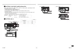
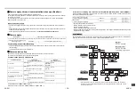
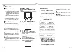
Wiring between indoor and outdoor units
NOTE
A wiring diagram below is an example for connection to SMMS-u series. For connecting to other outdoor unit series,
refer to the Installation Manual attached to the outdoor unit to be connected.
U1 U2
S
U4
U3
Uv
Uh
U6
L1 L2 L3 N
S U
Uc
5
U1 U2
S
U4
U3
Uv
Uh
U6
S U
Uc
5
L N
A B
L1 L2 L3 N
L N
A B
L N
A B
L N
A B
Uv(U1) Uv(U2)
A B
Uv(U1) Uv(U2)
A B
Uv(U1) Uv(U2)
A B
Uv(U1) Uv(U2)
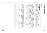
Outdoor Power supply
380-415V~,50Hz
380V~,60Hz
Circuit breaker,
Power switch
Remote controller
Indoor unit
Outdoor Power supply
380-415V~,50Hz
380V~,60Hz
Remote controller
Remote controller
Indoor unit
Indoor unit
Indoor unit
Circuit breaker
Circuit breaker
Outdoor unit
Header outdoor
Outdoor unit
Follower outdoor
Control wiring between outdoor units (Shield wire)
Control wiring between indoor and outdoor units (Shield wire)
Control wiring between indoor units (Shield wire)
Indoor power supply
220-240V~,50Hz
208-230V~,60Hz
Earth
Earth
Earth
Earth
Group control
Pull box
Pull box
Pull box
Earth
terminal
Earth
terminal
S: The ground of a shielded wire
S: The ground of a
shielded wire
▼Wiring example
▼Wiring example
▼Wiring example
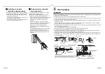
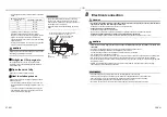
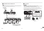
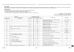
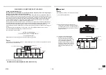
Wire connection
REQUIREMENT
• Connect the wires matching the terminal numbers. Incorrect connection causes a trouble.
• Pass the wires through the bushing of wire connection holes of the indoor unit.
• Keep a margin (Approx. 100 mm) on a wire to hang down the electrical control box at servicing or other purpose.
• The low-voltage circuit is provided for the remote controller. (Do not connect the high-voltage circuit)
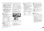
1. Before performing wiring work in the electrical control box, remove the cover of the box (fixed with 1 screw).
2. Tighten the screws of the terminal block firmly, and fix the wires with the cord clamp attached to the electrical
control box. (Do not apply tension to the connecting section of the terminal block.)
Mount the cover of the electrical control box without pinching wires.
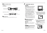
Earth screw
Control wire between
indoor and outdoor units
Remote controller wire
Power supply wire
Side C (Space: 4 mm)
Side D (Space: 8.5 mm)
Earth wire
2 mm or
less
Power supply wire
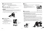
Select side C or D for the power supply wire clamping
position, refer to the following table according to the cord
type and diameter.
* The cord clamp can be attached on either right or left side.
Clamp two cords side-by-side for twin connection.
Cabtyre
cord
3-core stranded wire 2.5 mm²
Side D
2-core stranded wire 1.5 mm²
Side C
Control wire
between
indoor and
outdoor units
See the figure on
the left for system
interconnection
wires to the
terminal block.
Wire type
Specification
Cord clamping
position
43-EN
44-EN

