– 12 –
EN
23-EN
24-EN
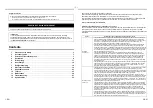
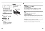
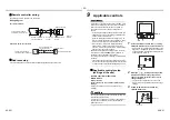
Pipe material, size and insulator
The following materials for piping work and insulating process are procured locally.
Connection of drain hose
• Connect a hard socket (locally procured) to the hard socket of the attached supplied flexible hose.
• Connect a drain pipe (locally procured) to the connected hard socket.
REQUIREMENT
• Connect hard vinyl chloride pipes securely using an adhesive for vinyl chloride to avoid water leakage.
• It takes some time until the adhesive is dried and hardened (refer to the manual of the adhesive). Do not apply
stress to the joint with the drain pipe during this time period.
Insert the flexible drain hose into the upper drain pipe and fix it with the hose band.
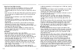
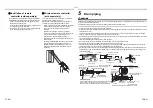
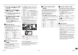
Gravitational drainage
1
Reattach the drain cap.
* For gravitational drainage, remove the white
connector (CN504) on the upper left of the circuit
board in the electrical control box.
2
Insert flexible drain hose into lower drain pipe
and fix it with hose band.
3
Remove drain pump connector CN504.
Pipe material
Hard vinyl chloride pipe VP25 (Nominal outer diameter 32 mm)
Insulator
Foamed polyethylene foam, thickness: 10 mm or more
Upper pipe
Hose band
Flexible
drain hose
Lower pipe
Upper pipe
Red
CN504
Black
Move the drain cap from
the lower pipe to the
upper pipe.
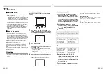
Drain up
When a down-gradient cannot be secured for the drain pipe, drain-up
piping is possible.
• The height of the drain pipe must be A mm or less from the
underside of the indoor unit.
• Take the drain pipe out of the drain pipe joint with the indoor unit in
250 mm or less, and bend up the pipe vertically.
• Immediately after the pipe is bent up vertically, lay the pipe making
a down-gradient.
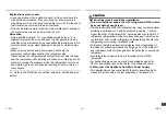
Check the draining
In the test run, check that water drain is properly performed and water does not leak from the connecting part of the
pipes. When doing this, also check that no abnormal sounds are heard from the drain pump motor. Check draining
also when installed in heating period.
When the electrical and wiring work has been completed
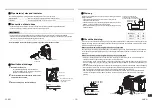
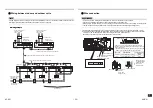
Pour some water by following the method shown in the following figure. Then, while performing a cooling operation,
check that the water drains from the drain pipe connecting port (transparent) and that no water is leaking from the
drain pipe.
When the electrical and wiring work has not been completed
• Disconnect the float switch connector (3P: red) from the connector (CN34: red) on the P.C. board inside the
electrical control box. (Before doing this, the power must be turned off.)
• Connect a 208 V to 240 V supply voltage to (L) and (N) on the power supply terminal block. (Do not apply a 208 V
to 240 V voltage to (Uv (U1)), (Uv (U2)), (A), (B) of the terminal block. Otherwise, the printed circuit board may be
damaged.)
• Pour the water by following the method shown in the following figure. (Amount of water poured: 1500 cc to 2000 cc)
• When the power is turned on, the drain pump automatically starts running. Check whether the water is draining
from the drain pipe connecting port, and check that no water is leaking from the drain pipe.
• After checking that the water drains and there are no water leaks, turn off the power, connect the float switch
connector to its original location (CN34) on the P.C. board, and return the electrical control box to its original
position.
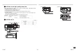
Drain up setup dimensions
For drain pipes that will be
connected after setup, make a
downward slope of 1/100 or more.
Flexible drain hose
(Accessory)
250 or less
B o
r
le
ss
A o
r
le
ss
Model type
A
B
003-012
550
380
015-018
650
480
024-027
750
580
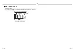
220-240V, 50Hz
208-230V, 60Hz
White
Red
Black
Black
Pull out connector CN34
(Red) from P.C. board.
Access panel
Supply water hose


