


EM SERVER FAN REPLACEMENT
System Fan Failure
15-10
Installation Manual June, 2011
EM SERVER FAN
REPLACEMENT
Four 4-cm heavy duty counter-rotating fans provide the cooling for the EM
server.
Each fan unit is actually made up of two fans joined back-to-back, which
rotate in opposite directions. This counter rotating action generates
exceptional airflow and works to dampen vibration levels.
The chassis top cover must be properly installed, making a good seal in
order for the cooling air to circulate properly through the chassis and cool
the components. Refer to
System Fan Failure
Fan speed is controlled by system temperature via a BIOS setting. If a fan
fails, the remaining fan will ramp up to full speed and the overheat/fan fail
LED on the control panel will turn on. Replace any failed fan at your
earliest convenience with the same type and model (the system can
continue to run with a failed fan).
Replacing EM System
Fans
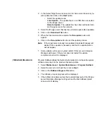
1. Remove the top chassis cover while the system is still running to
determine which of the fans has failed.
2. After determining which fan has failed.
3. Shutdown the IP
edge
server. Refer to
Remove Server Power
After the IP
edge
server has shutdown set both rear panel power switches
to OFF. Then unplug the power cords.
WARNING!
Remove the power cords before continuing this
procedure.
4. Unplug the fan cable from the server board and remove the failed fan
from the chassis.
5. Replace the failed fan with an identical 4-cm, 12-volt fan available
from Toshiba.
6. Push the new fan into the vacant space in the housing while making
sure the arrows on the top of the fan (indicating air direction) point in
the same direction as the arrows on the other fans.
7. Reposition the fan housing back over the two mounting posts in the
chassis, then reconnect the fan wires to the same chassis fan
headers you removed them from.
8. Power up the system and check that the fan is working properly and
that the LED on the control panel has turned off. Finish by replacing
the chassis cover.
Power UP Server
1. Connect the AC Power cords.
2. Set the rear panel switches to ON.
3. Wait one minute then, press the front panel Power Switch.
Summary of Contents for IPedge
Page 1: ...TOSHIBA Telecommunication Systems Division Installation Manual Title Page June 2011 ...
Page 18: ...This page is intentionally left blank ...
Page 32: ...This page is intentionally left blank ...
Page 46: ...This page is intentionally left blank ...
Page 74: ...This page is intentionally left blank ...
Page 78: ...This page is intentionally left blank ...
Page 88: ...This page is intentionally left blank ...
Page 92: ...This page is intentionally left blank ...
Page 96: ...This page is intentionally left blank ...
Page 140: ...MEDIANT 1000 CONFIGURATION IPedge Configuration 12 20 Installation Manual June 2011 ...
Page 196: ...THIS IS THE END OF THE DOCUMENT ...


