background image


16 


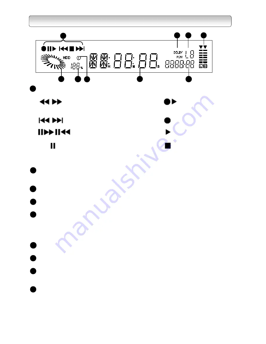
FP DISPLAY 


Operation Indicator 

Fast Reverse or Fast Forward

Ext. Rec. 

Skip Reverse or Skip Forward

Recording 

Frame Forward or Frame Reverse

Playback

Playback PAUSE

Stop


HDD Operation Indicator

 Animates when recorder is in HDD playback or recording mode else it 

 indicates used HDD storage space 

HDD Storage Indicator

 Indicates percentage of remaining HDD storage space  

Timer Recording Indicator

 Illuminates when the recorder has scheduled program for recording

Time and Channel Display

 a) Shows time as default (HH:MM) in 12 or 24 hours

 b) Shows channel number for 5 seconds after every channel change

 c) Shows HH:MM:SS during playback and recording mode

 d) Shows progress of Automatic Software Upgrade

Video Format Indicator

 Indicates current HD or SD display format including 1080i, 720p, 576p and 576i

Audio Format Indicator (PCM/Dolby)


Indicates current audio format 

Auxiliary Input Indicator (L1/L2)

 Indicates source of input through which external devices are connected. (e.g. DVD player)

 L1 = Component Video Input, L2 = Composite Video Input

Volume Indicator

 Displays the audio output level 

 Level indicator may not show exact sound level, it only shows the average level

1

3

4

2

5

6

7

8

9


1

2

3

4

5

6

7

8

9

(Flashing)


Summary of Contents for HDD-J35

Page 1: ...Toshiba Corporation DVB registration identification reference number 3253 Trade Mark of the DVB Digital Video Broadcasting Project 1991 to 1996 9 17 31 55 61 67 INTRODUCTION STARTUP GUIDANCE RECEIVING RECORDING PLAYBACK APPENDICES ...

Page 2: ...mage to the unit 1 Connect the power plug to AC 100 240V 50 60Hz 2 Unplug the power cord from the recorder before connecting any other equipment especially the TV antenna Connect all equipment to the recorder before plugging any power cords to the power source 3 Be sure your TV antenna is not located near overhead power lines or where it might fall into any power lines Also be careful to avoid tou...

Page 3: ...e this recorder immediately after moving it from a cold location to a warm location After moving leave the recorder in the warm location for TWO TO THREE hours without operating it so as to dry the moisture condensation naturally Moisture condensation is most likely to occur in the following cases When moved from a cold location to a warm location In a room rapidly heated or in a place where the r...

Page 4: ...the recorder and remove the power plug from the wall socket immediately Consult the local dealer for service Ignoring this condition may cause the damage of the HDD to be aggravated NOTES ON RECORDING When you record important contents make trial operations beforehand to ensure the recorder can function properly Toshiba does not compensate for content that was not recorded because of some malfunct...

Page 5: ...he top cover or rear panel may become warm after operating for a long time This is not a malfunction Do not use insecticide sprays etc near the unit Also do not leave rubber or plastic objects in contact with the unit for long periods of time This may cause discoloring of this unit s finish Keep the original packing that this unit came in and use it to re pack the unit when moving or transporting ...

Page 6: ... misuse or malfunction through simultaneous use of this product and the connected equipment Thank you very much for purchasing this Toshiba Digital HD Receiver and HDD Recorder HDD J35 In order to enjoy the many features this recorder has to offer read this owner s manual thoroughly before using We hope that you are completely satisfied with your Toshiba Digital HD Receiver and HDD recorder and it...

Page 7: ...G TO AMPLIFIER 24 6 CONNECTING TO MAINS SUPPLY 25 STEP B PREPARING YOUR REMOTE CONTROL 25 STEP C SETTING UP YOUR RECORDER 27 VIEWING PROGRAMS 29 TURNING OFF THE RECORDER 29 STATUS DISPLAY 30 CHAPTER THREE 31 RECEIVING 31 TOP MENU 31 TOP MENU 32 MENU MAP 32 MAIN MENU 33 INSTALLATION 33 QUICK SCAN For Australia Only 34 AUTO SCAN For Australia Only 34 MANUAL SETUP 35 RESET DATA 35 FORMAT HARD DISK 36...

Page 8: ...RECALL 53 CHAPTER FOUR 55 RECORDING 55 RECORDING METHODS 56 OTR ONE TIME RECORDING 56 TIME BASED RECORDING 57 EPG RECORDING 58 CHAPTER FIVE 61 PLAYBACK 61 LIBRARY 62 QUICK CONTROL 63 TIME LINE BAR 63 PLAYBACK 63 PLAYBACK PAUSE 65 STOP 65 FAST FORWARD FAST REVERSE 3 SPEEDS 65 SKIP FORWARD REVERSE 65 SLOW FORWARD SLOW REVERSE 3 SPEEDS 65 FRAME FORWARD FRAME REVERSE 65 INSTANT SKIP 65 CHAPTER SIX 67 ...

Page 9: ...Chapter One INTRODUCTION Introduction 10 Identification of Controls 1 Front Panel 11 2 Rear Panel 12 3 FP Display 14 4 Remote Control 15 ...

Page 10: ...tween Ź Chase Play This feature gives you the convenience of starting the playback from the beginning of the program currently being recorded without disrupting the recording continuously With this function you enjoy better control over the playback of recorded contents as you do not need to spend time waiting helplessly especially when recording a long program Ź Dolby Digital 2 Dolby Digital is t...

Page 11: ...i 720p 576p and 576i video output formats TOP MENU button Activates the On Screen Menu EXIT button Exits from the main menu or returns to the Main menu from submenu ENTER button Selects the highlighted menu or submenu item Directional buttons Move the selection focus on the screen Left and right buttons for increasing and decreasing audio volume Up and down buttons on front panel changes main prog...

Page 12: ...l control HD MODE Switch To switch HD output mode between RGB and YPBPR YPBPR IN L1 For connection to external A V equipment with component video outputs e g DVD player AUDIO L R IN For connection to external A V equipment with analogue audio outputs e g DVD player used together withYPBPR IN COMPOSITE VIDEO L R IN L2 For connection to external A V equipment with composite video outputs e g DVD pla...

Page 13: ...nection to TV s HDMI input DIGITAL AUDIO COAXIAL OUT For coaxial connection to an amplifier equipped with a Dolby Digital decoder DIGITAL AUDIO OPTICAL OUT For optical connection to an amplifier equipped with a Dolby Digital decoder ANALOG AUDIO L R OUT For connection to VCR or TV s Audio L R Audio inputs INTRODUCTION ...

Page 14: ...14 REMOTE CONTROL 4 5 6 7 8 9 10 11 12 13 14 15 16 17 1 3 2 18 19 20 21 22 23 24 25 26 27 28 29 30 31 32 33 34 35 36 37 38 39 40 41 42 43 INTRODUCTION ...

Page 15: ...TER button Page 11 42 CHANNEL NUMBER buttons Page 29 13 EXIT button Page 11 43 CC DIGIT SELECTION button Page 50 77 14 TOP MENU button Page 33 15 RECORD button Page 56 16 FAST REVERSE button Page 65 TV FUNCTION Set the Remote Control Unit to function with the Television Set See RCU programming guide on page 77 17 PLAY PAUSE button Page 63 and 65 18 SKIP REVERSE button Page 65 SET TOP BOX Set the R...

Page 16: ...s default HH MM in 12 or 24 hours b Shows channel number for 5 seconds after every channel change c Shows HH MM SS during playback and recording mode d Shows progress of Automatic Software Upgrade Video Format Indicator Indicates current HD or SD display format including 1080i 720p 576p and 576i Audio Format Indicator PCM Dolby Indicates current audio format Auxiliary Input Indicator L1 L2 Indicat...

Page 17: ...Read this chapter first to make all necessary preparations 1Installing the Recorder 18 Connections 18 Preparing your remote control 25 Setting up your recorder 27 2 Viewing programs 29 3 Turning off the recorder 29 4 Status display 30 ...

Page 18: ... built twin RF tuners connect the RF Coaxial Connectors supplied to the RF 1 OUT and ANT 2 IN terminals as shown in the diagram below 1 3 RF OUT Connection to TV or VCR The RF 2 OUT provides you a RF loop through function to receive analogue TV programs as well as digital programs for Integrated Digital TVs only Use an RF coaxial cable not supplied to connect the HDD J35 RF 2 OUT terminal to TV s ...

Page 19: ... c being the best choice a HDMI connection If your TV has HDMI input use a HDMI cable not supplied to connect the recorder to your TV HDMI supports video and multi channel audio in a single cable therefore separate connection for audio is not necessary HDMI cable not supplied To TV HDMI input HDD J35 L R L R SD VIDEO OUT RGB COAXIAL OPTICAL DIGITAL AUDIO OUT S VIDEO Y G PB B PR R H V VIDEO HDMI HD...

Page 20: ...your TV has RGBHV video inputs use a RGBHV video cable not supplied to connect the recorder to your TV Set the HD MODE Switch refer to page 12 to RGB and then connect the Y G PB B PR R H and V connectors from HD VIDEO OUT on the rear of the recorder to the corresponding jacks on the TV RGBHV video cable not supplied To TV RGBHV video inputs G B R H V H V HDD J35 Match the colors when connecting RG...

Page 21: ...O OUT PR RGB YPBPR HD MODE Note This diagram illustrates video connections only Refer to Page 22 for Audio connection e S Video connection If your TV has an S Video input use an S Video cable not supplied to connect the recorder to your TV Set the HD MODE Switch refer to page 12 to YPBPR and then connect the S Video connector from SD VIDEO OUT on the rear of the recorder to the corresponding jack ...

Page 22: ...ou can connect the recorder to your TV or to an audio amplifier equipped with a Dolby Digital decoder If you do not have an external amplifier equipped with a Dolby Digital decoder use the red and white connectors of the Audio Video cable included in the package Connect the audio connectors from ANALOG AUDIO OUT on the rear of the recorder to the corresponding jacks on the TV red to red right audi...

Page 23: ...6i ONLY white red Important 1 This setup is only for output connection made via HDMI 2 The YPBPR input connectors on this recorder accepts only 576i signal therefore the DVD player connected must be set to output in interlaced format Refer to your DVD player s manual for settings 3 CONNECTING TO CABLE BOX SATELLITE BOX VCR A cable box satellite box or VCR can be connected to this recorder through ...

Page 24: ...L OPTICAL DIGITAL AUDIO OUT Y G PB B PR R H V VIDEO HDMI HD VIDEO OUT ANALOG AUDIO OUT Audio Video cable supplied 5 CONNECTING TO AMPLIFIER If you connect this recorder to an audio amplifier equipped with a Dolby Digital decoder use an optical or coaxial digital cable not supplied to connect from the recorder s DIGITAL AUDIO OUT Optical Coaxial to the digital audio input of your amplifier In this ...

Page 25: ...r plug In other regions use the appropriate power plug Wall Outlet HDD J35 Power Cord supplied STEP B PREPARING YOUR REMOTE CONTROL Loading batteries 1 Open the Cover 2 Insert two R6 AA size batteries Make sure to match the and signs on the batteries to the marks inside the battery compartment 3 Close the cover STARTUP GUIDANCE ...

Page 26: ...ttery corrosion If the remote control does not function correctly or if the operating range becomes reduced replace all batteries with new ones If battery leakage occurs wipe the battery liquid from the battery compartment then insert new batteries Operating with the remote control 30O Within about 5m 30O 1 Point the remote control at the remote sensor and press the buttons 2 Distance About 5 m fr...

Page 27: ...order or on the remote control 4 A message Database is Empty should appear after a while If you can see the message go to Step 5 directly However if you cannot see the message on the screen even after a long time change the video format by pressing V FORMAT button on remote control or on the front panel Press V FORMAT button until you see the message Database is Empty Note When you press V FORMAT ...

Page 28: ...hoices of AUTO SCAN and QUICK SCAN are for Australia only 8 If you use QUICK SCAN in step 7 and when you see the message SCAN COMPLETE press the EXIT button several times until the main menu disappears 9 After you finish scanning you can choose the suitable V FORMAT If you use an SDTV use the V FORMAT 576i If you use a HD ready TV you are recommended to change to AUTO by pressing V FORMAT button H...

Page 29: ...ranged according to the Program list or Favorite Channel List depending on your current viewing mode See I PLATE INFO on page 47 for more information on viewing modes 2 Press the INFO button to view details on a program 3 Press the EPG button to view the Electronic Program Guide on a weekly basis 4 Press the VOLUME UP DOWN buttons to increase or decrease the audio volume or press the MUTE button t...

Page 30: ...the TV screen to indicate the status of the recorder Eg Status Display List of Status Display 3 3 3 3 Playback Playback Pause Stop Fast Forward 3 speeds Fast Reverse 3 speeds Skip Forward Skip Reverse Slow Forward 3 speeds Slow Reverse 3 speeds Frame Forward Frame Reverse Record Ext Rec ...

Page 31: ... List 38 EPG 38 System 39 Video Setup 39 Audio Setup 40 Password 40 Time Setup 41 Ext Control 41 Edit channel 42 Favorite Lock 42 Parental Rate 43 Virtual Keyboard 43 Profile 44 I Plate Setup 44 FP Display Setup 45 Information 45 PVR Setup 46 2Quick Control Info 47 TV Radio 48 EPG 48 Fav 49 PIP 49 TTX 50 CC 50 Freeze 50 V Format 51 A Ratio 51 Input Select 52 Sleep 52 Audio 53 Recall 53 ...

Page 32: ...ON page 33 SYSTEM page 39 PROFILE page 44 I PLATE SETUP page 44 FP DISPLAY SETUP page 45 PVR SETUP Page 46 VIDEO SETUP page 39 AUDIO SETUP page 40 PASSWORD page 40 TIME SETUP page 41 EXT CONTROL page 41 FAVORITE LOCK page 42 PARENTAL RATE page 43 QUICK SCAN page 34 AUTO SCAN page 34 MANUAL SETUP page 35 RESET DATA page 35 INFORMATION page 45 FORMAT HARD DISK page 36 S W UPDATE page 36 Note If you ...

Page 33: ...e main menu 4 Menu s left displayed for 15 minutes will exit automatically INSTALLATION On the main menu select INSTALLATION and key in your password to enter the INSTALLATION page The default password is 0000 Refer to page 40 to change the password If you are in Australia you have choices of MANUAL SETUP AUTO SCAN QUICK SCAN to tune the recorder If you stay in other region use MANUAL SETUP to tun...

Page 34: ...the local TV Radio station changes the channel frequency or a new channel comes up you have to scan these channels using MANUAL SETUP 2 Recorder is defaulted to TV mode instead of Radio mode after QUICK SCAN AUTO SCAN For Australia Only The AUTO SCAN feature allows you to scan all predefined digital TV and Radio channels in Australia The steps required to automatically program the recorder are out...

Page 35: ...at too strong a signal may cause erroneous readings If you use an antenna booster and find that you still get a low signal level your booster gain may be set too high In this case adjust the gain accordingly You may also see the OSD Bad or No Signal or Weak Signal when the signal level is low QUALITY refers to the quality of the received digital signal A high value of quality means that there are ...

Page 36: ...r 1 Highlight S W UPDATE and press the ENTER button 2 Use the Ż and Ź buttons to highlight between YES and NO 3 Before you select YES follow the steps outlined below to configure your PC first a Connect PC to your HDD J35 recorder with a crossed over RS232 cable cable for null modem b On the PC side Launch the HyperTerminal application Name the connection Select the correct COM port usually COM1 U...

Page 37: ...ALLATION instructions on page 33 Note It is safe to turn off the recorder only after the recorder has booted up automatically Do not disconnect the recorder from the power source during the software update process If there is a power failure during this time the recorder may become unusable In this case contact your local dealer Over time Automatic Software Upgrade service will be available as bro...

Page 38: ...al buttons to highlight a channel 3 Press the ENTER button to preview a channel and show Now Next info Refer to page 47 I PLATE INFO for details 4 To exit from the PROGRAM LIST press the EXIT button Note Another way to call up the PROGRAM LIST is via the TV Radio button on the remote control Refer to TV Radio on page 48 for details EPG Electronic Program Guide 1 Highlight the EPG and press the ENT...

Page 39: ...D OUTPUT FORMAT Use the Ż and Ź buttons to switch among video formats 576i for HD MODE Switch being set to YPBPR only AUTO 1080i 720p and 576p In AUTO mode the recorder switches the video output format to the same as sent by the broadcaster automatically Otherwise the recorder will fix its video output at the format you have selected SD OUTPUT FORMAT This setting cannot be changed ASPECT RATIO Use...

Page 40: ...ins more than one type of digital audio output use the Ż and Ź buttons to switch between the available options PCM and Dolby Digital Note You need to connect the recorder to an amplifier with Dolby Digital decoding capability via DIGITAL AUDIO optical port or coaxial port when Dolby Digital option is selected Refer to page 22 for the connection details Otherwise you may encounter softer audio from...

Page 41: ...e residing in For Australia Use the Ż and Ź buttons to select the local time zone you are located in For other region Use the Ż and Ź buttons to set your local time EXT CONTROL For details of controlling the HDD J35 recorder by an external device connected via the RS 232 serial port consult your local dealer RECEIVING ...

Page 42: ... ź buttons to select a channel and the Ż and Ź buttons to highlight a or cell 2 When a cell is highlighted press the ENTER button to perform the following Toggles locking and unlocking a channel Toggles adding and removing from Fav channel list Deletes the highlighted channel 3 Channel names can be edited by using the virtual keyboard 4 To activate the virtual keyboard shift cursor over channel na...

Page 43: ...4 5 6 7 8 1 3 2 KEYPAD Keying of alphabet characters and symbols SPACEBAR Keying of a single space between characters BACKSPACE Erases one character immediately to the left side of the cursor CLEAR ALL Erases all the characters on the input column CAPS LOCK Caps lock BACKSPACE Red colour button Erases one character immediately to the left side of the cursor SAVE Green colour button Saves the chang...

Page 44: ...se the Ÿ and ź buttons to highlight the options I PLATE SETUP FP DISPLAY SETUP INFORMATION PVR SETUP I PLATE SETUP 1 Highlight I PLATE SETUP and press the ENTER button 2 Use the Ÿ and ź buttons to highlight Display Time or Time Format 3 Use the Ż and Ź buttons to change the values of the highlighted options 4 For more information on I PLATE refer to page 47 ...

Page 45: ...lay brightness In OFF state the ON STANDBY LED indicator will light up in red colour Notes 1 TIME mode sets the recorder s front panel Time and Channel Display to show current time The displayed current time is purely based on the time sent by the broadcaster of the channel you are currently viewing which may not be accurate 2 When the recorder is in off air mode CHANNEL NUMBER sets the recorder s...

Page 46: ... and press the ENTER button 2 Under INSTANT SKIP INTERVAL use the Ż and Ź buttons to choose between 30 sec 1 min 3 min or 5 min This will change the instant skip interval 3 For more information on INSTANT SKIP INTERVAL refer to page 65 ...

Page 47: ...t a reminder on the next program If the reminder will start at the same time with a reminder you have set previously you can choose to press ENTER to replace or EXIT to cancel SNR value Indicates Favorite viewing mode In Favorite viewing mode Ÿ ź CHŸ and CHź buttons allow you to navigate programs in the Favorite Channel List 4 When I PLATE is still on the TV screen you can press the INFO button ag...

Page 48: ...ou open the EPG window If you are recording through Video Output do not use the EPG function 2 A weekly calendar is presented Use the YELLOW and BLUE buttons to select a day 3 Use the directional buttons Ÿ ź Ż and Ź to select a program 4 Press the ENTER button to show the program details in a new popup window Press the ENTER button again for Current Program only to exit EPG and watch that program ...

Page 49: ...e press the TV RADIO button or any CHANNEL NUMBER buttons of a non favorite program PIP Picture in Picture 1 PIP feature is applicable for High Definition and Standard Definition format programs PIP also displays sources from Auxiliary Input L1 L2 2 When watching a TV program not in the main menu press the PIP button on the remote control to bring up the PIP window 3 The last seen off air program ...

Page 50: ... the function is not permitted in TTX mode 2 To speed up Teletext browsing pages you have visited previously will be stored internally in the recorder If you re visit a page you may see old contents being displayed initially but the page will be updated as soon as new information is received from the broadcaster 3 If you leave a fixed text for a long period of time a permanent afterimage may remai...

Page 51: ...AL If this setting is selected and your program is in 16 9 both sides of the picture will be cut off to fill your 4 3 TV Use 4 3 LETTERBOX This setting allows you to display a 16 9 program on a 4 3 TV screen in letterbox with masking bars above and below the picture If this viewing is continued for a long period of time it may cause a permanent image burn to the TV screen If you are using a 16 9 T...

Page 52: ...nds and the timer starts OFF 30 min 60 min 90 min 120 min To check the remaining time 1 Once the off timer has been set press SLEEP button once 2 Current remaining time is displayed on the screen and then turns off after 5 seconds To change the off timer 1 Once the off timer has been set press SLEEP button once 2 Current remaining time is displayed on the screen Before the OSD turns off press SLEE...

Page 53: ...o cancel the list RECALL The RECALL button is used to toggle between present and previous programs 1 In the case you are viewing Program A and then you change to Program B You can press the RECALL button on the remote control to return to previous program A 2 Press the RECALL button again and the recorder will show Program B 3 This function also toggles between TV and Radio programs ...

Page 54: ...54 ...

Page 55: ...55 Chapter Four RECORDING Recording Methods 1OTR One Time Recording 56 2 Time Based Recording 57 3 EPG Recording 58 ...

Page 56: ...OP button to end recording 5 Viewing another channel during a recording process can be achieved by just selecting another channel 6 If two OTR recordings are taking place at the same time select the desired channel to display on the main window and press STOP button to stop the recording 7 If viewing auxiliary input L1 L2 while recording is going on STOP and PLAY PAUSE button will not have effect ...

Page 57: ...EXIT buttons to go in and out of these smaller menus Take note that the menu legend changes after the BLUE button is pressed 4 Under the respective subjects use the Ÿ and ź buttons to select between different values Channel Name Select desired channel to record Press enter to select Mode Select between Once Daily or Weekly Press enter to select Date Select date of recording Editable only for Once ...

Page 58: ...ram a recording It will take less time to prepare as it provides all necessary information for recording 1 Before recording ensure that there is sufficient space remaining in the HDD Delete unwanted files or archive some files using VCR to create space for recording Refer to Library Menu and External Recording in the next chapter for instructions on deleting and archiving files 2 Press the EPG but...

Page 59: ...d menu and press the STOP button 9 Refer to next section on Playback to view recorded programs Notes 1 When there s a power failure or accidental removal of the power plug during recording all recordings will resume automatically when the set top box is powered up again However previously on going recordings will be lost 2 When one or two recording is going on and PIP is switched on there are cert...

Page 60: ...60 ...

Page 61: ...ine bar 63 Playback Normal Playback 63 Pause TV Playback 63 Chase Play 64 Playback Pause 65 Stop 65 Fast Forward 3 speeds 65 Fast Reverse 3 speeds 65 Skip Forward 65 Skip Reverse 65 Slow Forward 3 speeds 65 Slow Reverse 3 speeds 65 Frame Forward 66 Frame Reverse 66 Instant Skip 66 ...

Page 62: ...files to be deleted and press the RED button 7 To rename a file select the file and press the GREEN button A virtual keyboard will appear to facilitate renaming Refer to page 43 on the usage of the virtual keyboard 8 To mark a file select the file and press the BLUE button Press the BLUE button again to unmark 9 To do External Recording Mark files to record to external recorders in numbering order...

Page 63: ...eric buttons to skip forward a certain percentage of the program according to the number pressed i e 1 10 9 90 5 Press the TIME BAR or EXIT button to switch off the Time Line Bar display Pause TV Playback 1 This function allows you to pause a TV broadcast and resume viewing at a later more convenient time by storing the TV broadcast temporarily on the HDD 2 While viewing a TV broadcast via this re...

Page 64: ...order displays a TV program as it is being recorded 3 Press the REVERSE SKIP button to go to the beginning of the recorded program and playback starts automatically 4 Press TIME BAR to determine location from current broadcast 5 During playback operations like Fast Forward Reverse Slow Forward Reverse and Frame Forward Reverse can be performed to locate a specific scene In particular Fast Forward ...

Page 65: ...SLOW REVERSE 3 SPEEDS To play in slow motion press the SLOW FORWARD or SLOW REVERSE button Each time a button is pressed the playback speed changes To resume normal playback press the PLAY PAUSE button Note Slow motion does not provide smooth playback FRAME FORWARD FRAME REVERSE To play frame by frame press the PAUSE button followed by FAST FORWARD or FAST REVERSE button Each time the button is pr...

Page 66: ...66 ...

Page 67: ... Chapter Six APPENDICES 1Australian DTV Channel Table 68 2 Troubleshooting 70 3 Parental Guidance Codes 72 4 Glossary 73 5 Technical Specifications 75 6 Instruction Guide For Programming Remote Control 77 ...

Page 68: ...e Digital 7 VHF 6 177 5MHz Mt Dandenong 1 1 2001 Digital 9 VHF 8 191 625MHz Mt Dandenong 1 1 2001 Digital 10 VHF 11 219 5MHz Mt Dandenong 1 1 2001 Digital ABC VHF 12 226 5MHz Mt Dandenong 1 1 2001 Digital SBS UHF 29 536 5MHz Mt Dandenong 1 1 2001 Perth Digital 7 VHF 6 177 5MHz Carmel 1 1 2001 Digital 9 VHF 8 191 625MHz Carmel 1 1 2001 Digital 10 VHF 11 219 5MHz Carmel 1 1 2001 Digital ABC VHF 12 2...

Page 69: ... 5MHz Knights Hill Digital 10 UHF 37 592 5MHz Knights Hill Digital PRIME UHF 38 599 5MHz Knights Hill 30 6 2002 Digital ABC UHF 51 690 5MHz Knights Hill 30 6 2002 Digital SBS UHF 54 711 625MHz Knights Hill 30 6 2002 Hobart SthCrossTas VHF 10 212 5MHz Mt Wellington Digital Win VHF 7 184 5MHz Mt Wellington Digital ABC VHF 8 191 625MHz Mt Wellington Digital SBS VHF 9A 205 5MHz Mt Wellington Digital 1...

Page 70: ...vailable after using AUTO SCAN when installing the recorder for the first time Try MANUAL SETUP to scan these missing channels This phenomenon is caused by unexpected frequency offset for instance in Sunshine Coast Australia channels 47 and 65 are transmitted on 662 625 and 788 625MHz by 125kHz offset to the legitimate frequencies 662 5 and 788 5MHz HDD J35 can receive these channels by AUTO SCAN ...

Page 71: ... reinstallation 3 Incorrect Password Input the correct password 4 Program under Parental Control Input the correct password or change parental rate see page 43 to view the program 5 Program Locked Input the correct password or change lock setting in menu see page 42 to view the program 6 Weak Signal Make sure antenna or signal input cable is connected correctly HD MODE Switch Selection HD MODE Out...

Page 72: ...72 3 PARENTAL GUIDANCE CODES APPENDIX ...

Page 73: ...by Intel Corporation to protect digital entertainment content across the HDMI interface HDMI Abbreviation for High Definition Multimedia Interface HDMI combines high definition video and multi channel audio in a single digital interface to provide crystal clear digital quality over a single cable Letterbox The picture with aspect ratio 16 9 in a 4 3 TV screen with blank lines on top and bottom It ...

Page 74: ...cy starts from 300 to 3000MHz corresponding to channels 13 69 including Bands IV and V Y PB PR Color difference signal which is better than S Video and Composite Video in terms of picture quality Y PB and PR are the standard video connectors found in HDTVs 6 576p is classified as HD format in Australia However it may be classified as SD format in some other regions ...

Page 75: ...ys Channel Clock Display 4 6 Digits Rear Panel Tuner Input 2 RF PAL Female Tuner Output 2 RF PAL Male Serial Port 1 RS 232 for external control and software upgrading Video Output Mode Switch 1 HDMI Output Port 1 RGBHV Output Port 5 RCA 1 x Mini D Sub 15 pin Y PB PR Video Output Port 3 RCA Shared with RGB in RGBHV Output Port Digital Audio Output Port 1 S PDIF Optical 1 S PDIF Coaxial S Video Outp...

Page 76: ...76 Accessories Remote Control CT 90195 1 Audio Video cable 1 Component Video cable Y PB PR 1 Power cord 1 RF Loop through cable 1 R6 AA size battery 2 Owner s Manual 1 ...

Page 77: ...ng the CHANNEL NUMBER buttons d Check response on LED with every digit pressed 1 LED lights up after the first digit press 2 LED blinks once after the second digit press 3 If the code is available LED goes off after the third digit press or else the LED will blink twice and goes off indicating unavailable code Go back to step c if an unavailable code was entered e Release PROG button to leave the ...

Page 78: ... code you wish to know The number of blinks in the LED represents the code if there is no blink the code is 0 d LED goes off and remote control exits Brand code display mode if the TV button is pressed or no further activity is sensed after ten seconds 4 Auto code search This function is similar to Auto code search Region except that a forward search in the code list is performed for all regions a...

Page 79: ...73 Granada UK 002 004 027 041 044 045 046 047 048 049 Grundig 003 010 018 020 045 050 051 053 054 056 094 Hanseatic 025 027 037 044 052 055 258 Hantarex 269 Hauppaugel 026 Hemmermann 057 Hinari 033 044 058 059 060 Hitachi 004 040 041 042 044 047 055 061 062 063 064 065 066 067 068 174 221 222 280 Hotel TV 274 Hyper 003 004 033 153 193 Imperial 019 023 024 145 151 169 170 231 Inno Hit 004 031 043 0...

Page 80: ...3 026 027 046 073 113 115 155 191 192 193 194 223 230 242 266 Phonola 175 Pilot 1624Y 299 PIP Pilot P1277Y 291 Pilot P3033 297 Pilot P4005 296 Pilot P567 298 Pilot P286 294 Pioneer 027 067 243 269 Polestar 214 Prandoni Prince 008 032 146 Praxis 217 Prosat 001 Quelle 004 005 007 008 009 010 013 026 027 028 045 050 051 052 069 094 153 221 231 232 234 235 236 253 Radiola 242 Rank UK 022 RBM UK 022 09...

Page 81: ...414 JBL 418 JCB 461 JVC 417 467 472 KEC 440 Kenwood 406 Kloss 409 414 KTV 413 440 441 446 467 LG 420 Luxman 420 LXI 404 418 430 431 460 470 471 Magnavox 407 409 411 418 425 436 439 442 443 449 465 467 Marantz 411 418 MEI 441 Majustic 403 Matsushita 445 Megatron 402 427 Memorex 403 420 421 428 430 445 MGA 406 411 429 MGA Mitsubishi 473 Midland 404 412 413 Minutz 408 Mitsubishi 406 424 428 438 Motor...

Page 82: ...24 Tatung 402 419 471 Technics 404 415 416 445 460 Technika 403 406 413 418 420 421 423 428 439 440 442 472 Technol Ace 439 Techwood 402 420 Telefunken 420 Teknika 467 TMK 420 437 438 Toshiba 421 430 431 470 471 472 Tosonic 441 Totevision 413 467 Trical 432 Universal 408 410 Vector research 411 Victor 417 Vidikron 418 Vidtech 406 438 Viking 414 Wards 407 408 410 411 418 420 425 426 431 434 438 439...

Page 83: ...626 678 682 684 685 686 691 697 700 709 714 715 716 718 721 800 801 803 805 808 823 908 Haier 701 740 Hisense 632 637 638 641 677 681 683 723 724 754 755 757 758 760 768 775 829 840 Hitachi 628 634 637 638 669 679 690 692 695 699 714 716 727 738 754 755 757 758 760 763 764 777 Imperialcown 607 648 649 664 762 765 770 771 774 775 777 782 823 835 Infinity 682 908 JBL 682 908 JC Penney 655 Jinxing 60...

Page 84: ...4 Sampo 651 676 773 775 776 Samsung 626 640 651 686 700 714 715 716 718 721 773 775 776 781 800 805 808 837 Sanyo 627 637 638 648 663 678 681 694 696 710 717 734 754 757 760 765 768 770 771 818 Scott 651 737 Sears 717 737 768 798 Sharp 687 689 706 712 720 743 748 773 775 806 807 815 Sherwood 773 775 Sky Worth 636 641 681 683 684 685 686 718 742 744 745 773 793 801 803 805 808 868 869 870 871 872 8...

Page 85: ... 808 816 819 675 773 775 773 775 614 621 637 648 765 770 771 773 775 684 685 686 718 801 803 805 808 676 773 775 606 816 819 678 648 676 765 770 771 607 621 648 649 664 676 684 685 686 718 762 765 770 771 773 774 775 777 781 782 791 801 803 805 808 814 823 835 0 641 648 676 678 683 765 770 771 803 1 676 773 775 782 676 773 775 1 2 676 684 685 686 718 773 775 801 803 805 808 1 3 676 773 775 1 4 773...

Page 86: ...1 803 805 808 676 684 685 686 718 760 801 803 805 808 773 775 606 684 685 686 718 801 803 805 808 816 819 648 765 770 771 773 775 676 773 775 621 684 685 686 718 773 775 801 803 805 808 648 676 684 685 686 718 765 770 771 773 775 801 803 805 808 773 775 637 676 684 754 755 760 676 684 685 686 718 791 796 801 803 805 808 676 686 765 775 782 805 812 813 814 835 648 676 765 770 771 0 2 648 676 765 77...

Page 87: ...87 MEMO ...

Page 88: ...88 2005 Toshiba Corporation Printed in Taiwan ...

Reviews: