background image

SERVICE MANUAL

PLAIN


PAPER


FACSIMILE


e-STUDIO

191F 

File No. SME

11

00

5

00

0

R

110

3

21

J12

00

-TTEC

Ver0

0

_20

11

-0

4

Summary of Contents for e-studio191f

Page 1: ...SERVICE MANUAL PLAINPAPERFACSIMILE e STUDIO191F File No SME11005000 R110321J1200 TTEC Ver00_2011 04 ...

Page 2: ...too high about 1100 F 600 C ECO SOLDER M705 available from Senju Metal Industry Co Ltd URL http www senju m co jp is recommended when repairing PbF PCBs This Product Uses Lead Pb Free Solder Printed Circuit Boards PCBs This service information is designed for experienced repair technicians only and is not intended for use by the general public It does not contain warnings or cautions to advise non...

Page 3: ...able s if connected 3 Unplug the AC Power Cord Reference There is a remote possibility of electrocution when servicing the unit during a Lightning Storm As a precaution disconnect the Telephone Line Cable first before unplugging the AC Power Cord The specifications are subject to change without notice TOSHIBA TEC CORPORATION reserves the right to make improvements in the product design without res...

Page 4: ...nt near the outlet Be sure to wire the power cable securely so as to unplug Depending on your machine s model it may weight approximately 47 40 lb 21 5 kg without any options To prevent injuries use the appropriate number of personnel and lift or move the machine as illustrated Do not lift the machine by the Paper Tray as it may cause damage and or bodily injury Note Refer to the Operating Instruc...

Page 5: ... damaged cord can cause fire or electric shocks Never touch a power cord with wet hands Danger of electric shock exists If the power cord is damaged or insulated wires are exposed contact the authorized TOSHIBA dealer for a replacement Using a damaged cord can cause fire or electric shocks Stop operation immediately if your machine emits smoke excessive heat unusual noise or abnormal smell or if w...

Page 6: ...he machine configuration or modify any parts An unauthorized modification can cause smoke or fire Consumable Safeguards Never dispose of toner toner cartridge or a waste toner container into an open flame Toner remaining in the cartridge bottle can cause an explosion burns and or injuries Installation and Relocation Cautions Do not place the machine near heaters or volatile flammable or combustibl...

Page 7: ...ventilated when using the machine for an extended period of time to minimize the ozone density in the air When copying with the document cover open do not look directly at the exposure lamp Direct eye exposure can cause eye fatigue or eye injury Pull the paper trays out slowly to prevent injuries When removing jammed paper make sure that no pieces of torn paper are left in the machine A piece of p...

Page 8: ...lug them into outlets operating on different circuits Reorient the TV and or radio antennas and cables until the interference stops For an outdoor antenna ask your local electrician for support Use a coaxial cable antenna Discarding of P C Board When discarding P C Board delete all personal information such as telephone directory and caller list or scrap P C Board Precautions to Prevent Damage fro...

Page 9: ...py Quality Problems 97 4 4 Document Feeder ADF 111 4 5 Communications 114 4 6 Troubleshooting the LAN Interface 119 4 7 Error Codes For Copier 126 4 8 Information Code Table For Facsimile 131 4 9 Diagnostic Codes For Facsimile 138 4 10 Troubleshooting For Printer 146 Service Modes 148 5 1 Service Modes For Copier 148 5 2 Service Modes For Facsimile 162 System Description 187 6 1 Transmit Mechanism...

Page 10: ...nsmission Speed Approx 2 7 sec ITU T Image No 1 A4 Std Resolution 7 Communication Resolution dpi x lpi pels mm x lines mm Transmission Std 203 x 98 8 x 3 85 Fine 203 x 196 8 x 7 7 S Fine 203 x 391 8 x 15 4 406 x 391 16 x 15 4 600dpi 600 x 600 dpi Reception Std 203 x 98 8 x 3 85 Fine 203 x 196 8 x 7 7 S Fine 203 x 391 8 x 15 4 406 x 391 16 x 15 4 600dpi 600 x 600 dpi 600 dpi communication is only p...

Page 11: ...06 x 391 16 x 15 4 dpi x lpi pels mm x lines mm LTR 5 7 sec A4 6 1 sec 150dpi 150 x 150 LTR 1 1 sec A4 1 1 sec 300dpi 300 x 300 LTR 2 2 sec A4 2 3 sec 600dpi 600 x 600 LTR 8 8 sec A4 9 3 sec 3 Document Size Max Legal 8 5 x 14 in 216 x 2000 mm 4 Effective Scanning Width LTR 8 3 in 212 mm A4 8 2 in 208 mm Letter size for USA and Canada A4 size for Other Destinations 5 ADF Capacity 100 sheets Face Up...

Page 12: ...ided Copy Yes 2 1 Only Power Supply 1 Power Requirement 99 132 VAC 47 63 Hz Single phase 120 VAC 50 60 Hz 2 Power Consumption Standby 11 W 120 VAC Power Supply Transmission 20 W Reception 830 W Copy 830 W Maximum Less than 1000 W Ambient Conditions 1 Temperature 50 80 F 10 30 C 2 Relative Humidity 30 80 RH 3 Safety UL60950 1 CSA C22 2 No 60950 1 For USA and Canada 4 EMI Class B computing device pe...

Page 13: ...itional 420 stations available to select from when the optional SD Memory Card Max 2GB is installed 6 Total Auto Dialers 580 Max 1 000 7 Program Dials 80 8 Max Number Digits Fax 36 9 Max Number Digits Email 60 10 Max Station Name Characters 15 11 Full Number Dialing Buffered Dialing Yes Max 50 stations 12 Direct Dialing Monitor Dialing Yes Voice mode 13 Automatic Redialing Yes Up to 15 times at 0 ...

Page 14: ...mission Yes Real Time up to 5 Files 11 90 Degree Rotation Transmission No 12 Cover Sheet Yes 13 Confidential Mail Box No 14 Multi Copy Transmission No 15 Memory Back Up Yes FAX Back up with Flash Memory Copy Printer No Back up with D RAM 16 Duplex Scanning Yes Scan twice Fax once Reception Features 1 Substitute Reception Yes 2 Fixed Reduction Yes LTR A4 LGL 70 100 in 1 Steps Top Left Alignment 3 A...

Page 15: ...res 1 First Copy Time Letter 27 sec A4 28 sec 2 Copy Speed Letter Approx 19 cpm Paper Feed 1st Paper Tray Paper Exit to Exit Tray Continuous Copy Mode A4 Approx 18 cpm 3 Single Copy Yes 4 Multiple Copy Yes 5 Sort Copy Yes 6 Enlargement Yes 7 Reduction Yes 8 Zoom Yes 71 141 Certainty 1 Verification Stamp Yes 2 Header Total Page Print Yes 3 Transaction Journal Yes 200 Transactions with View Mode 4 C...

Page 16: ...b address XMT Yes 12 Sub address Auto Routing Yes 13 Internet Fax Relay XMT Yes Internet Fax Internet Fax G3FAX 14 Email Relay XMT Yes PC Internet Fax G3FAX 15 Fax Driver Yes Others 1 Fax Access Code Yes 2 PIN Code Access Yes For USA and Canada only 3 Intelligent Redial AI Yes 5 Files 4 Department Code Yes 50 Departmental Codes 5 Power Saver Mode Yes 6 Self Diagnostic Function Yes 7 Check Call Fun...

Page 17: ...Win 7 7 Printer Work Memory Size 22 MB Not expandable 8 GDI Yes 9 PDL PCL6 No 10 PDL PS3 No 11 Duplex Printing No 12 Collation Stack Yes 13 Status Monitor Network Yes USB No 14 Network Status Monitor Yes 15 Smoothing Yes 16 Applicable PC IBM PC AT or Compatible 17 Multi Task Operation Printing while Fax XMT from Memory Yes Printing while Fax RCV into Memory Yes Fax XMT from Memory while Printing Y...

Page 18: ... A4 1 1 sec 300dpi 300 x 300 LTR 2 2 sec A4 2 3 sec 600dpi 600 x 600 LTR 8 8 sec A4 9 3 sec Color No 3 Halftone 256 Halftone shades With Error Diffusion 4 Max Document Size Legal 8 5 x 14 in 216 x 356 mm 5 Scanning Resolution dpi Mono 600 x 600 300 x 300 150 x 150 Default 300 dpi 6 OS Win 2000 Win XP Win 2003 Win Vista Win 7 7 2 Sided Scanning No 8 File Format Multi page TIFF PDF 9 Completion Noti...

Page 19: ... 391 16 x 15 4 600dpi 600 x 600 dpi LAN 600 dpi 16 x 15 4 Scanning Resolution is available Printer Mechanism 1 Printing Resolution 600 dpi 2 Effective Recording Width LTR 8 1 in 207 mm A4 7 9 in 201 mm Transmission Features 1 Multi Task Operation Yes Convenient simultaneous G3 Fax and LAN operation 2 Memory Transmission Yes 3 Sequential Multi Station Transmission Yes 4 Simultaneous Multi Station T...

Page 20: ...t available Phone Book Registration from PC Yes Via Email or Network Address Editor 4 Internet Fax Parameters Registration via Email Yes 5 Internet Delivery Confirmation Yes With MDN 6 Network Scanning Yes 600 dpi 7 Network Printing LPR LPD Yes 600 dpi GDI Yes 600 dpi PDL No 8 DHCP Client Yes 9 LDAP Yes Lightweight Directory Access Protocol 10 TIFF Viewer Yes Selectable TOSHIBA DMS TIFF Viewer Cer...

Page 21: ... SD Memory Card stores approximately 50 420 pages of PCL bitmap print data 6 Once the SD Memory Card is installed the standard Fax Internet Fax Flash Memory and the Network Scanning D RAM is no longer used 7 Max page number may differ depending on the manufacturer of the SD Memory Card SD Memory Card Format Structure SD Memory Size 32 MB 64 MB 128 MB 256 MB 512 MB 1 GB 2 GB Max Number of Pages 1 0...

Page 22: ...22 DP 1910F 1 2 Control Panel For USA and Canada TOSHIBA DP 1910F ...

Page 23: ...tion Standard Configuration Panel PNL PC Board Handset Kit Option USB Interface GDI Printer 10 100 Ethernet Interface Automatic Document Feeder ADF Internet Fax Email Network Scanner Module Option G3 Communication Port Kit Option Electronic Sorting Memory DP 1910F Std Super G3 Fax Communication SPC PCB SPC PCB ...

Page 24: ...2 Availability may differ as per destination Please ask your sales company for detail Option Name Option Number Remarks G3 Communication Port Kit GD 1310 2nd Paper Feed Module KD 1030 Handset Kit GJ 1170 SD Memory Card 32 MB up to 2 GB SDHC SDXC is not supported Part Name Part Number Remarks Toner Cartridge PS ZT1910 For USA and Canada ...

Page 25: ... in 440 mm 17 72 in 450 mm 15 83 in 402 mm 14 17 in 360 mm Front View Right View Left View Rear View Top View Manufacturer s Name and Address Factory ID Complies with FDA radiation performance standards 21 CFR Subchapter J For USA Only 20 71 in 526 mm 19 06 in 484 mm 4 88 in 124 mm 17 48 in 444 mm 19 80 in 503 mm 17 32 in 440 mm 17 72 in 450 mm ...

Page 26: ...48 in 444 mm 19 80 in 503 mm 19 80 in 503 mm 11 18 in 284 mm 11 18 in 284 mm 3 94 in 100 mm 7 09 in 180 mm 43 19 in 1097 mm 3 94 in 100 mm 3 94 in 100 mm 3 94 in 100 mm 41 89 in 1064 mm 17 48 in 444 mm 19 80 in 503 mm 17 48 in 444 mm 19 80 in 503 mm 9 45 in 240 mm 9 45 in 240 mm Main Unit Handset Option 4 33 in 110 mm Main Unit 11 18 in 284 mm 11 18 in 284 mm ...

Page 27: ...uction Number 5 Digit Sequential Production Number 10001 99999 1 99 999 units D UF 8200 UZ Production Year 1 2011 2 2012 3 2013 Production Month A January G July B February H August C March I September D April J October E May K November F June L December 7 8 9 Production Number C CHINA FACTORY Production Facility For Example ...

Page 28: ...Motor Registration Solenoid Pick Up Solenoid Clutch PNL3 PNL2 PNL1 HVPS Document Eject Sensor Read Point Sensor Document Sensor CIS CRB ADF Door Sensor Exit Sensor PCB Exit Sensor Exit Sensor Actuator Paper Path Sensor Actuator Registration Sensor Actuator Registration Sensor Paper Path Sensor Registration Sensor PCB SPC FXB LVPS SC ...

Page 29: ... Control Panel Unit 2 3 1 Top Cover 2 3 1 Fuser Unit 2 3 7 Bias Transfer Roller 2 3 9 Right Cover 2 3 1 Paper Feed Module 2 3 7 Paper Exit Sensor 2 3 7 Control Panel Unit 2 3 3 LSU Unit 2 3 6 SC PCB 2 3 4 MJR PCB 2 3 4 SPC PCB 2 3 4 LVPS 2 3 4 HVPS 2 3 4 Drive Unit 2 3 5 ADF Unit 2 3 2 Stamp Unit 2 3 2 Roller Assembly 2 3 2 ...

Page 30: ...ulations are assembled under strict factory control If the procedures are marked with Caution follow the instructions carefully and making sure that all parts are properly installed to conform the regulations Automatic Document Feeder ADF Unit Scanner 2 3 2 Control Panel Unit Bias Transfer Roller 2 3 3 2 3 9 Paper Feed Module 2 3 8 PC Board 2 3 4 2nd Paper Feed Module 2 3 10 Cover Assembly 2 3 1 L...

Page 31: ... Exit Cover 1 Remove the Rear Cover 604 Refer to 2 3 1 1 Rear Cover 2 Remove 3 Screws 3 Remove the Exit Cover 602 Caution When reinstalling the Exit Cover make sure 2 Latches are fitted inside of the Inner Cover 3 Control Panel Unit 1 Remove the Rear Cover 604 Refer to 2 3 1 1 Rear Cover 2 Remove the Exit Cover 602 Refer to 2 3 1 2 Exit Cover 3 Open the Right Cover 614 4 Remove 2 Screws 5 Remove t...

Page 32: ...er 604 Refer to 2 3 1 1 Rear Cover 2 Remove the Exit Cover 602 Refer to 2 3 1 2 Exit Cover 3 Remove the Control Panel Unit Refer to 2 3 1 3 Control Panel Unit 4 Open the ADF Cover Assembly 5 Remove 3 Screws 6 Lift the ADF Tray Assembly 7 Remove 2 Screws 8 Release the Latch Hook on the Top Cover 601 ...

Page 33: ...Remove the Exit Cover 602 Refer to 2 3 1 2 Exit Cover 3 Remove the Control Panel Unit Refer to 2 3 1 3 Control Panel Unit 4 Remove the Top Cover 601 Refer to 2 3 1 4 Top Cover 5 Pull the Paper Tray out 6 Remove 2 Screws 7 Remove 2 Screws 8 Release the Speaker Harness from 1 Clamp 9 Disconnect the Speaker Harness 10 Remove the Front Cover Assembly ...

Page 34: ...Refer to 2 3 1 4 Top Cover 5 Remove the Front Cover Assembly Refer to 2 3 1 5 Front Cover Assembly 6 Loosen 6 Screws 7 Remove the SC Cover 714 8 Release 2 Harnesses from 2 Clamps and 1 Edge Saddle 9 Disconnect 2 Harnesses on the SC PC Board CN519 CN520 Caution When reconnecting the Harnesses insert the Power 2 Harness into the Edge Saddle as illustrated to comply with EMI regulations 10 Remove 6 S...

Page 35: ...13 Disconnect 5 Harnesses on the SPC PC Board CN701 CN706 CN709 CN710 and CN714 14 Release the Harness from 1 Clamp Edge Saddle and 1 Flat Clamp 15 Disconnect the Harness on the SC PC Board CN502 16 Remove 3 Screws on the Rear Side 17 Remove 3 Screws on the Front Side ...

Page 36: ...he ADF Cover Assembly Refer to 2 3 1 4 Top Cover Separation Roller Pick Up Roller and Feed Roller Clean the surface of the Rollers with a soft cloth saturated with water ADF Pad Clean the surface of the ADF Pad only with a soft dry cloth CIS Contact Image Sensor Clean the surface of the CIS only with a soft dry cloth White Sheet Clean the surface of the White Sheet only with a soft dry cloth ...

Page 37: ...sembly Separation Roller Assembly 1 Open the ADF Cover Assembly Refer to 2 3 1 4 Top Cover 2 Remove the Separation Roller Cover 438 as illustrated 3 Remove the Snap Ring 4 Remove the Separation Roller Assembly as illustrated 5 Remove the Separation Roller Shaft Assembly 440 Pick Up Roller 416 6 Remove 2 Screws 7 Remove the Upper Paper Guide 311 ...

Page 38: ... the Hook as illustrated 9 Remove both side Feed Levers 402 10 Remove the Roller Assembly 11 Remove the Snap Ring 12 Remove the Pick Up Shaft 412 13 Remove the Pick Up Roller Assembly 14 Remove the Pick Up 1 Gear 414 and Pick Up 2 Gear 413 ...

Page 39: ... Assembly Refer to 2 3 1 4 Top Cover 2 Remove the Stamp Unit Refer to 2 3 2 2 Stamp Unit 3 Remove the Upper Paper Guide 311 Refer to 2 3 2 3 Roller Assembly 4 Remove 3 Screws 5 Remove the Paper Guide 434 6 Remove 2 Screws 7 Remove the Paper Guide 433 8 Remove 2 Screws 9 Remove the CIS Assembly 10 Disconnect the Flat Harness from CIS Assembly Caution When reinstalling the CIS Assembly pull out the ...

Page 40: ...bly 3 Remove 2 Screws 4 Remove 2 Screws 5 Remove the ADF Base 538 6 Close the ADF Cover Assembly 7 Turn the ADF Drive Assembly upside down 8 Release the Paper Transfer Motor Harness from 7 Clamps 9 Unhook the Tension 2 Spring 332 10 Remove 3 Screws 11 Remove the Paper Transfer Motor Assembly 12 Remove 4 Screws 13 Remove the Paper Transfer Motor Assembly ...

Page 41: ...ration Roller Cover Refer to 2 3 2 3 Roller Assembly 17 Remove the Paper Guide 433 and CIS Assembly Refer to 2 3 2 4 CIS Contact Image Sensor Assembly 18 Remove 1 Screw 19 Remove the Plate Holder 509 20 Remove 1 Screw 21 Remove the Plate Holder 509 22 Remove 4 Screws 23 Remove the Separation Guide Plate Assembly 24 Disconnect the Harness on the Paper Feed Motor ...

Page 42: ... Disconnect all the Harnesses on PNL1 PC Board 3 Remove 4 Screws 4 Remove the PNL1 PC Board 1804 from the Spacer Note Remove the PNL1 PC Board by nipping the spacer with a pliers as illustrated 5 Remove 20 Screws 6 Remove the PNL2 PC Board 1806 LED Module and LCD Module 7 Remove 2 Screws 8 Remove the LED Module 9 Remove the PNL3 Board 1805 from the Lamp Cover 10 Remove the LCD Module 111 ...

Page 43: ...ws 7 Remove the MJR Bracket 715 Refer to 2 3 1 6 ADF Drive Assembly SC PC Board 8 Remove 1 Screw 9 Remove the Ground Plate 713 10 Disconnect all Harnesses on the SC PC Board 11 Remove 2 Clamps from the SC Bracket 12 Remove 8 Screws 13 Remove the SC PC Board 1701 14 Release all Harnesses from all Clamps and Egde Saddles on the SC Bracket 15 Remove 8 Screws 16 Remove the SC Bracket 708 SPC PC Board ...

Page 44: ...ge to the Latch and secure with 2 Screws 23 Remove the LVPS 1706 HVPS 24 Remove the Front Cover Assembly Refer to 2 3 1 5 Front Cover Assembly 25 Remove 6 Screws 26 Remove the HVPS Insulation Sheet 816 27 Remove the HVPS 817 28 Disconnect the Harness on the HVPS 1 Motor 1 Remove the Rear Cover 604 Refer to 2 3 1 1 Rear Cover 2 Disconnect the Harness on the Motor Assembly 3 Remove 3 Screws 4 Remove...

Page 45: ...Assembly 8 Remove the Snap Ring 9 Remove the Pick Up Roller Clutch 921 10 Release 3 Harnesses from 4 Clamps 11 Disconnect 3 Harnesses on the SPC PC Board CN731 CN732 CN741 12 Disconnect the Harness on the Motor Assembly 13 Remove 3 Screws 14 Remove the Drive Unit Caution 1 When removing the Drive Unit exercise care not to drop lose the Gears 2 When reinstalling please make sure the Gears are posit...

Page 46: ... clean or make adjustments when the Fuser Unit is hot 1 Fuser Unit 1 Remove the Exit Cover 602 Refer to 2 3 1 2 Exit Cover 2 Remove the Inner Cover 606 3 Release the Harness from 1 Clamp 4 Disconnect 2 Harnesses 5 Remove 3 Screws 6 Remove the Fuser Unit 1334 7 Remove 2 Screws 8 Remove the Fuser Holder R 1330 ...

Page 47: ...10 Remove 2 Screws 11 Remove the Fuser Holder L 1331 12 Remove 2 Screws 13 Remove the Side Fuser Cover 1306 14 Remove 2 Screws 15 Remove the Left Fuser Cover 1316 16 Remove 2 Black Screws 17 Separate the Upper Fuser Unit 18 Remove the Pressure Roller 1326 ...

Page 48: ...on Do not Touch the glass portion of the Fuser Lamp with bare hands Grease from finger prints will shorten its life cycle use isopropyl alcohol to clean finger prints 21 Shift the Fuser Roller and remove the Left Heat Roller Bushing 1323 22 Remove the Heat Roller 1322 23 Remove the Heat Roller Gear 1320 and the Right Heat Roller Bushing 1321 24 Remove 3 Screws 25 Remove 2 Thermostats 1303 ...

Page 49: ... Remove 4 Separator Springs 1311 29 Remove 4 Screws 30 Remove 4 Separator Plates 1312 31 Remove 4 Separators 1313 2 Paper Exit Sensor 1 Remove the Exit Sensor PC Board 1802 by unhooking 2 Latches as illustrated 2 Remove the Connector from the Exit Sensor PC Board ...

Page 50: ...lastic Sheet 2 Pick Up Roller 1 Remove the Rear Cover 604 Refer to 2 3 1 1 Rear Cover 2 Open the Right Cover 614 Refer to 2 3 1 3 Control Panel Unit 3 Pull the Paper Tray out Refer to 2 3 1 5 Front Cover Assembly 4 Remove the Toner Cartridge 5 Remove the Snap Ring 6 Remove the Pick Up Roller Clutch 921 7 Remove the Stopper 611 as illustrated 8 Remove 2 Screws 9 Remove the Paper Guide 1120 10 Turn ...

Page 51: ... Toner Cartridge 3 Remove 2 Transfer Roller Holder 901 4 Remove the Bias Transfer Roller Assembly 5 Remove the Spacer 902 6 Remove the Transfer Gear 903 7 Remove 2 Bushings 904 8 Remove the Spacer 902 1 Remove 5 Screws 2 Remove the Rear Cover 1501 3 Open the Jam Cover Assembly 4 Remove the Jam Cover Assembly by pulling the Hook as illustrated ...

Page 52: ...P 1910F 5 Remove 2 Screws 6 Remove the Paper Guide 1120 7 Remove the Snap Ring 8 Remove the Pick Up Roller Clutch 1612 9 Turn the Pick Up Roller Assembly 10 Remove 2 Screws 11 Remove 2 Pick Up Rollers 1106 ...

Page 53: ...g the unit apart do not attempt to operate the machine 2 When operating the machine with covers removed be careful and avoid clothing from being caught by moving components 3 While the electricity is applied to the unit do not connect nor disconnect the connectors on any PC Board 4 When handling the drum follow the precautions listed in section 3 3 5 Ensure to use correct screws 6 Use toothed lock...

Page 54: ...ry Card on the SC PCB Physically break the SD Memory Card or completely delete the data using a data deleting software 7 To secure the customer s information make sure the Fax number E mail address is set correctly in the Check Call feature 8 Service Manuals and Installation Instructions are essential for maintaining security of the machine Service Technicians are required to bring back the Instal...

Page 55: ...ith the previously printed one 2 Auto Document Feeder ADF Check Clean 1 Clean the Rollers with Wet soft cloth Water Note For stubborn toner accumulation wipe with a soft cloth saturated with Isopropyl Alcohol first then follow up with a soft cloth saturated with water 3 Scanner Unit Check Clean 1 Clean the Scanning Glass or White Reference Sheet with Isopropyl Alcohol when required 2 Clean it with...

Page 56: ...ive Maintenance Points Pick Up Roller Separation Roller ADF Pad Feed Roller 1 3 4 LSU Toner Cartridge Feed Roller 9 Bias Transfer Roller BTR 7 Pick Up Roller 8 Fuser Unit 10 2 CIS Contact Image Sensor White Sheet OPC Drum 5 6 ...

Page 57: ...ic Counter 00 List Print 3 Cleaning Replacement and Adjustment Cycle Sheet are based on using TOSHIBA s recommended standard paper and supplies These cycles may vary with the kind of paper used Paper size orientation print duty continuous interval print and or ambient conditions No Preventive Maintenance Parts Ref No Cleaning Replacement Adjustment Ref Counter Cycle Sheet Method Cycle Sheet Proced...

Page 58: ...nication protocol Control is saved on the Board The Firmware is transferred as Serial Data from the SC PCB D Firmware Updating Ports Three 3 types of Ports are available for updating the firmware 1 Ethernet LAN Port The machine s Firmware can be updated using a PC via Local Area Network LAN 2 USB Port The machine s Firmware can be updated using a PC via USB Port 3 SD Memory Card Convenient Method ...

Page 59: ... connected to a LAN 1 Install the Network Firmware Update Tool to your PC The Tool can be downloaded from your sales company s Web Site Please refer to the Tool s Operating Instructions file for additional details 2 Preparing the Firmware Code Access the Service Web site to download the latest Firmware Code When performing the self extraction wizard for preparing the Firmware Code File the Archive...

Page 60: ... to your PC The Tool can be downloaded from your sales company s Web Site Please refer to the Tool s Operating Instructions file for additional details 2 Preparing the Firmware Code Access the Service Web site to download the latest Firmware Code When performing the self extraction wizard for preparing the Firmware Code File the Archive will be extracted automatically into the designated folder Ex...

Page 61: ...ct the Telephone Line LAN and or USB Cables 3 Unplug the AC Power Cord to turn off power During a Lightning Storm to prevent electrocution disconnect the Telephone Line Cable first before unplugging the AC Power Cord 4 Install the appropriate Master Firmware SD Memory Card into the machine 5 Plug the AC Power Cord to turn on power 6 Press the Function Original Size and the 3 keys sequentially 7 In...

Page 62: ...ther than factory default Note After the update is completed the machine reboots itself and returns to standby mode Selecting the Auto Mode prompts the unit to check the configuration and installed options and all the necessary firmware is updated automatically Confirm that the update was successfully completed by checking the Firmware Version with F9 Parameters F9 02 xx Caution If the unit does n...

Page 63: ... the Stop key first and press the Function Clear keys sequentially to exit the Service Mode 11 Unplug the AC Power Cord to turn off power 12 Remove the SD Memory Card from the machine 13 Plug the AC Power Cord to turn on power 14 Reconnect the Telephone Line LAN and or USB Cables Note Repeat steps 7 to 12 to continue formatting other SD Card s 2 When a DATA SD Card is installed 1 Disconnect the Te...

Page 64: ...l If the unit does not boot up properly follow the steps below 1 Turn the power OFF Before proceeding to the next step you must create the Master SD Memory Card read the appropriate sections first 3 5 5 2 Turn the power On while holding the ENERGY SAVER button 3 When the green lamp on the front panel turns On release the ENERGY SAVER button The unit is now ready to accept the firmware code from Ma...

Page 65: ...he tray setting to the appropriate paper size Empty all the remaining trays including the bypass tray to disable them Note Do not pull out the 1st tray to disable it when adjusting the 2nd tray The 1st tray is required as it acts as a paper path for the paper in the 2nd tray 2 Press the Function Original Size and the 3 keys sequentially 3 Input the ID and press the Set key to enter the Service Mod...

Page 66: ...nal Read Edge 8 If the gap is less than the Original input a value If bigger than the Original input a value 9 Perform the Service Mode F6 90 ADF Image Read Start to adjust the ADF Main Scan for Side position 10 If the gap is less than the Original input a value If bigger than the Original input a value 11 Press the Stop key first and press the Function Clear keys sequentially to exit the Service ...

Page 67: ...r Supply Live ACN AC Power Supply Neutral AGND Ground B Motor Control Signal BB Motor Control Signal BZCLK Buzzer Signal Output CCLK Serial I F Clock CISCLK CIS Clock CLOCK_OP CLOCK CXD Serial Data Command FANNERR Fan Error Detection Signal FANPER 24VDC Fan Power FG Ground GND Ground IICSCL IIC Bus Clock IICSDA IIC Bus Data KIN0 PNL Key Signal Key Line KIN1 PNL Key Signal Key Line KIN2 PNL Key Sig...

Page 68: ...NG3B Ringer Detection Signal nDB Developer Voltage PWM Pulse nDBCH Developer Charge Change nEXITSEN EXIT Sensor Signal nFCTL Fuser ON OFF Control nHKOFF External Phone Off Hook Detection Signal nHSYNC Horizontal Synchronization Signal nIRQG3B G3B Interrupt Request Signal nJAMDOR_OP 2nd Feeder Option Detection Signal nJAMDOR OP JAM Cover Sensor detect Signal nLDON LD Light Enable nLED1 PNL LED Cont...

Page 69: ...11 PNL Key Signal Scan Line nSCN 2 PNL Key Signal Scan Line nSCN 3 PNL Key Signal Scan Line nSCN 4 PNL Key Signal Scan Line nSCN 5 PNL Key Signal Scan Line nSCN 6 PNL Key Signal Scan Line nSCN 7 PNL Key Signal Scan Line nSCN 8 PNL Key Signal Scan Line nSCN 9 PNL Key Signal Scan Line nSLPKY Energy Saver Key Signal nSNRCLK LSU Motor Clock nSNRCTL LSU Motor Control Signal nSNRLD LSU Motor Lock Signal...

Page 70: ...st Signal PUSOL_CTL Pick Up Solenoid Control PUSOL_CTL1 Pick Up Solenoid Control pVREQ Scanner Vertical Synchronous Request Signal REGSOL_CTL Registration Solenoid Control SCLD0 IIC Bus Clock SDA0 IIC Bus Data SEL CIS Resolution Selection SI Scan Data Frame Signal SIG Scanner Serial Data SPCIIC IIC Bus SDR Interrupt SPKOUT Line Signal Dial Tone Ringer Key Tone SXD Serial Data Status TH Fuser Therm...

Page 71: ... PNL1 PCB CN230 11 24V 5V Power Control Signal CN501 6 BZCLK PNL1 PCB CN230 10 Buzzer Signal CN501 7 nPNLRST PNL1 PCB CN230 9 PNL Reset Signal CN501 8 PNLTXD PNL1 PCB CN230 8 PNL Transmission Data Signal CN501 9 PNLRXD PNL1 PCB CN230 7 PNL Reception Data Signal CN501 10 5V PNL1 PCB CN230 6 5 VDC Power Supply CN501 11 5VP PNL1 PCB CN230 5 5 VDC Power Supply CN501 12 GND PNL1 PCB CN230 4 Ground 0V 1...

Page 72: ...EL CRB PCB CN802 12 CIS Resolution Selection CN502 3 GND CRB PCB CN802 11 Ground CN502 4 5VA CRB PCB CN802 10 5VDC Power Supply CN502 5 VREF CRB PCB CN802 9 Dark Reference Control CN502 6 SI CRB PCB CN802 8 Scanner Data Frame Signal CN502 7 GND CRB PCB CN802 7 Ground CN502 8 CISCLK CRB PCB CN802 6 CIS Clock CN502 9 GND CRB PCB CN802 5 Ground SC PCB Pin No Signal Name Destination Signal Waveform Fu...

Page 73: ...504 2 nLPOW SPC PCB CN704 11 Power Save Control CN504 3 5VP SPC PCB CN704 10 5 VDC Power Supply CN504 4 5VA SPC PCB CN704 9 5 VDC Power Supply CN504 5 GND SPC PCB CN704 8 Ground CN504 6 GND SPC PCB CN704 7 Ground CN504 7 24V SPC PCB CN704 6 24 VDC Power Supply CN504 8 MGND SPC PCB CN704 5 Ground CN504 9 5V SPC PCB CN704 4 5 VDC Power Supply SC PCB Pin No Signal Name Destination Signal Waveform Fun...

Page 74: ...CN721 14 Ground CN505 4 nTOP SPC PCB CN721 13 Paper Top Detection Signal CN505 5 nSBSY SPC PCB CN721 12 Busy Status CN505 6 nHSYNC SPC PCB CN721 11 Horizontal Synchronization Signal CN505 7 pPRTRST SPC PCB CN721 10 Printer Reset CN505 8 nPURGE SPC PCB CN721 9 Paper End Detection Signal CN505 9 CXD SPC PCB CN721 8 Serial Data Command SC PCB Pin No Signal Name Destination Signal Waveform Function 5V...

Page 75: ...B CN721 1 Power Save Control Signal SC PCB Pin No Signal Name Destination Signal Waveform Function CN510 1 AGND G3B PCB CN363 14 Ground CN510 2 AOUTG3B G3B PCB CN363 13 Line Signal CN510 3 nCTONG3B G3B PCB CN363 12 Ringer Detection Signal CN510 4 nIRQG3B G3B PCB CN363 11 G3B Interrupt Request Signal CN510 5 GND G3B PCB CN363 10 Ground SC PCB Pin No Signal Name Destination Signal Waveform Function ...

Page 76: ...0 12 GND G3B PCB CN363 3 Ground CN510 13 3 3V G3B PCB CN363 2 3 3 VDC Power Supply CN510 14 5V G3B PCB CN363 1 5 VDC Power Supply SC PCB Pin No Signal Name Destination Signal Waveform Function CN518 1 GND SPC PCB P716 10 Ground CN518 2 SPCIIC SPC PCB P716 9 IIC Bus SDR Interrupt CN518 3 nSPCWAKE SPC PCB P716 8 Wake Up Control SC PCB Pin No Signal Name Destination Signal Waveform Function 3 3V 0V G...

Page 77: ... PCB P716 1 Scanner Horizontal Synchronous Signal SC PCB Pin No Signal Name Destination Signal Waveform Function CN519 1 5VP MJR PCB CN302 7 5VDC Power Supply CN519 2 GND SPC PCB CN302 6 Ground CN519 3 nHKOFF SPC PCB CN302 5 External Phone Off Hook Detection Signal CN519 4 nRING SPC PCB CN302 4 Ring Detection Signal CN519 5 pCMLD SPC PCB CN302 3 Line Switching Relay Drive Signal SC PCB Pin No Sign...

Page 78: ...CB Pin No Signal Name Destination Signal Waveform Function CN701 1 LDAPNT Document Sensor 3 1 2 VDC Power Supply CN701 2 GND Document Sensor 2 Ground CN701 3 nAPNT Document Sensor 1 ADF Paper Detection Sensor Signal CN701 4 LDCPNT Ejection Sensor 3 1 2 VDC Power Supply CN701 5 GND Ejection Sensor 2 Ground CN701 6 nCPNT Ejection Sensor 1 ADF Paper Ejection Sensor Signal SC PCB Pin No Signal Name De...

Page 79: ...LDADF DOOR ADF Door Sensor 3 1 2 VDC Power Supply CN706 5 N C ADF Door Sensor 2 No Connection CN706 6 pADF DOOR ADF Door Sensor 1 ADF Door Open Close Signal SPC PCB Pin No Signal Name Destination Signal Waveform Function CN709 1 24V STAMP Solenoid 1 24 VDC Power Supply CN709 2 MGND STAMP Solenoid 2 Ground SPC PCB Pin No Signal Name Destination Signal Waveform Function CN710 1 nB PH Motor 1 PH Moto...

Page 80: ...S CN103 4 24 VDC Power Supply CN712 5 MGND LVPS CN103 5 Ground CN712 6 MGND LVPS CN103 6 Ground CN712 7 MGND LVPS CN103 7 Ground CN712 8 5V LVPS CN103 8 5 VDC Power Supply CN712 9 5V LVPS CN103 9 5 VDC Power Supply CN712 10 GND LVPS CN103 10 Ground SPC PCB Pin No Signal Name Destination Signal Waveform Function 24V 0V 24V 0V 24V Sleep Mode 24V Shutdown Mode 0V 24V Sleep Mode 24V Shutdown Mode 0V 2...

Page 81: ...n CN714 1 nA ADF Motor 1 ADF Motor Control Signal CN714 2 A ADF Motor 3 ADF Motor Control Signal CN714 3 nB ADF Motor 4 ADF Motor Control Signal CN714 4 B ADF Motor 6 ADF Motor Control Signal SPC PCB Pin No Signal Name Destination Signal Waveform Function CN722 1 nADUST LSU PCB Laser Diode 1 LSU APC Timing CN722 2 nVIDEO LSU PCB Laser Diode 2 Video Signal SPC PCB Pin No Signal Name Destination Sig...

Page 82: ...5 VDC Power Supply CN724 2 5VGND CST2 PCB CN602 13 Ground CN724 3 pENABLE_OP CST2 PCB CN602 12 2nd Feeder Motor Control Signal CN724 4 nPON_OP CST2 PCB CN602 11 2nd Feeder No Paper Detection Signal CN724 5 nOPTION CST2 PCB CN602 10 2nd Feeder Option Detection Signal CN724 6 nPUCTL_OP CST2 PCB CN602 9 2nd Feeder Paper Pick up Control CN724 7 24VGND CST2 PCB CN602 8 Ground SPC PCB Pin No Signal Name...

Page 83: ...ET_OP CST2 PCB CN602 1 2nd Feeder Option Reset SPC PCB Pin No Signal Name Destination Signal Waveform Function CN726 1 24V Front Cover Safety Interlock SW 3 24 VDC Power Supply CN726 2 24VGND Front Cover Safety Interlock SW 5 Ground CN726 3 24VIR Front Cover Safety Interlock SW 1 24 VDC Power Supply SPC PCB Pin No Signal Name Destination Signal Waveform Function CN728 1 24VIR HVPS PCB CN501 10 24 ...

Page 84: ...R HVPS PCB CN501 3 Transfer Voltage PWM Pulse CN728 9 5V HVPS PCB CN501 2 5 VDC Power Supply CN728 10 nTECTL HVPS PCB CN501 1 Low Toner LED Control SPC PCB Pin No Signal Name Destination Signal Waveform Function CN729 1 nTESEN Low Toner Sensor CN803 2 Low Toner Sensor Signal CN729 2 5VGND Low Toner Sensor CN803 1 Ground SPC PCB Pin No Signal Name Destination Signal Waveform Function 0V 0V 5V 0V HV...

Page 85: ...Clock SPC PCB Pin No Signal Name Destination Signal Waveform Function CN731 1 PUSOL_CTL Pick Up Solenoid 1 Pick Up Solenoid Control CN731 2 24VGND Pick Up Solenoid 2 Ground SPC PCB Pin No Signal Name Destination Signal Waveform Function CN732 1 REGSOL_CTL Registration Solenoid 1 Registration Solenoid Control CN732 2 24VGND Registration Solenoid 2 Ground 24V 0V Sleep Shutdown 0V 5V 0V LSU Motor Con...

Page 86: ...or Signal CN734 5 nPLPOSISEN Registration Paper Detect Sensor PC Board CN805 1 Paper Lead Position CN734 6 LDEXITSEN Paper Exit Sensor PC Board CN803 3 1 2 VDC Power Supply CN734 7 5VGND Paper Exit Sensor PC Board CN803 2 Ground CN734 8 nEXITSEN Paper Exit Sensor PC Board CN803 1 EXIT Sensor Signal CN734 9 5V Thermistor 2 5 VDC Power Supply CN734 10 TH Thermistor 1 Fuser Thermistor Signal SPC PCB ...

Page 87: ... Main Motor 3 Main Motor Control Signal CN737 6 nMMLD Main Motor 2 Main Motor Rotation Signal CN737 7 nMMHALF Main Motor 1 Motor Rotation Speed Control H 1908 35 RPM L 954 18 RPM SPC PCB Pin No Signal Name Destination Signal Waveform Function CN738 1 FANPER Fan Motor 1 24VDC Fan Power SPC PCB Pin No Signal Name Destination Signal Waveform Function 5V 0V No Paper Sensor ON 1 2V 24V 5V 24 VDC throug...

Page 88: ...detect Sensor 1 Paper Tray detect Signal PNL1 PCB Pin No Signal Name Destination Signal Waveform Function CN234 1 nSCN 1 PNL2 PCB CN251 1 PNL Key Signal Scan Line CN234 2 nSCN 2 PNL2 PCB CN251 2 PNL Key Signal Scan Line CN234 3 nSCN 7 PNL2 PCB CN251 3 PNL Key Signal Scan Line CN234 4 nSCN 8 PNL2 PCB CN251 4 PNL Key Signal Scan Line CN234 5 nSCN 9 PNL2 PCB CN251 5 PNL Key Signal Scan Line SPC PCB P...

Page 89: ... PNL LED Control Signal CN234 13 nLEDSLP PNL2 PCB CN251 13 Energy Saver Lamp LED Control Signal CN234 14 5VP PNL2 PCB CN251 14 5 VDC Power Supply PNL1 PCB Pin No Signal Name Destination Signal Waveform Function CN235 1 5V PNL2 PCB CN252 1 5 VDC Power Supply CN235 2 nSCN 3 PNL2 PCB CN252 2 PNL Key Signal Scan Line CN235 3 nSCN 4 PNL2 PCB CN252 3 PNL Key Signal Scan Line PNL1 PCB Pin No Signal Name ...

Page 90: ...2 PCB CN252 11 PNL Key Signal Key Line CN235 12 KIN1 PNL2 PCB CN252 12 PNL Key Signal Key Line CN235 13 KIN0 PNL2 PCB CN252 13 PNL Key Signal Key Line CN235 14 nLED5 PNL2 PCB CN252 14 PNL LED Control Signal CN235 15 nLED8 PNL2 PCB CN252 15 PNL LED Control Signal CN235 16 nLED9 PNL2 PCB CN252 16 PNL LED Control Signal PNL1 PCB Pin No Signal Name Destination Signal Waveform Function 3 3V 0V Key Scan...

Page 91: ...ARM Lamp LED Control Signal CN236 3 nLEDACT PNL3 PCB CN254 3 ACTIVE Lamp LED Control Signal CN236 4 ACT PNL3 PCB CN254 4 ACTIVE Lamp LED Power Supply CN236 5 ALM PNL3 PCB CN254 5 ALARM Lamp LED Power Supply CN236 6 DAT PNL3 PCB CN254 6 DATA Lamp LED Power Supply PNL1 PCB Pin No Signal Name Destination Signal Waveform Function CN238 1 nLEDDBK PNL4 PCB CN253 1 PNL LCD Back Light Control Signal PNL1 ...

Page 92: ...9 Registration Paper Detect Sensor PC Board CN805 Refer to SPC PC Board CN734 3 7 10 Paper Exit Sensor PC Board CN803 Refer to SPC PC Board CN734 3 7 11 No Paper Sensor PC Board Refer to SPC PC Board CN736 3 7 12 Low Toner Sensor PC Board CN803 Refer to SPC PC Board CN729 3 7 13 HVPS CN501 Refer to SPC PC Board CN728 3 7 14 LVPS CN103 Refer to SPC PC Board CN712 CN238 2 VCC PNL4 PCB CN253 2 5VDC P...

Page 93: ...Control Signal CN600 3 24VA 2nd Feeder Motor 3 24 VDC Power Supply CN600 4 24VA 2nd Feeder Motor 4 24 VDC Power Supply CN600 5 BB 2nd Feeder Motor 5 2nd Feeder Motor Control Signal CN600 6 A 2nd Feeder Motor 6 2nd Feeder Motor Control Signal CST2 PCB Pin No Signal Name Destination Signal Waveform Function CN601 1 PUSOL_CTL1 Pick Up Solenoid 1 Pick Up Solenoid Control CN601 2 24V Pick Up Solenoid 2...

Page 94: ...sor 2nd 1 JAM Cover Sensor detect Signal CN603 4 LDPNON OP No Paper Sensor 2nd 3 1 2 VDC Power Supply CN603 5 GND No Paper Sensor 2nd 2 Ground CN603 6 nPNON OP No Paper Sensor 2nd 1 No Paper Sensor detect Signal CN603 7 LDCCHK OP Paper Tray detect Sensor 2nd 3 1 2 VDC Power Supply CN603 8 GND Paper Tray detect Sensor 2nd 2 Ground CN603 9 nCCHK OP Paper Tray detect Sensor 2nd 1 Paper Tray detect Si...

Page 95: ...inted copy quality problems Sect 4 3 Troubleshoot the Document Feeder Sect 4 4 Check for recording paper path problems TroubleshootImproper LCDDisplay Sect 4 2 Troubleshoot any 3 digit INFO CODE displayed Does the unit produce normal copies Troubleshoot communication problems transmission reception dialing network connection polling information codes or diagnostic codes Does the unit power up norm...

Page 96: ...4 Press the Lighter key or Darker key 5 Press the Set key or the Stop key Replace the SC PCB Is the trouble resolved Replace the Low Voltage Power Supply Unit Is the trouble resolved Check connectors on the SC PCB and PNL PCB Is LED LCD displayed Does the display appear normal Replace the LCD Module Replace the Panel Does CNP501 pin 11 on the SC PCB measure 5 VDC Yes Yes Yes Yes Yes No No No No No...

Page 97: ...onal Replace the Toner Cartridge 1 Check all connectors and voltages on the Power Supply Unit 2 Check the contacts between PSU and TonerCartridge 3 Replace the PSU Yes No Yes Yes No No 1 Check all connectors and voltages on the SC PCB 2 Replace the SC PCB END Is the printout in Service Mode 3 normal Is the SPC PCB normal Yes No 1 Check all connectors and voltages on the SPC PCB 2 Replace the SPC P...

Page 98: ...voltages on the Power Supply Unit 2 Check the Connector and voltage on the Power Supply Unit 3 Replace the Power Supply Unit Are there any foreign particles or stains blocking the Laser Beam path Yes No Is the SC PCB normal 1 Remove the particles from the laser beam path or clean the stains 2 Replace the Laser Unit LSU 1 Check all connectors and voltages on the SC PCB 2 Replace the SC PCB Yes No I...

Page 99: ... 2 Replace the BTR Yes No Clean or replace the rollers No Yes Check the Scanner mechanism No Yes Yes Is the recording paper damp Is the Toner Cartridge operational 1 Remove the particles from the laser beam path or clean the stains 2 Replace the Laser Unit LSU Are there any foreign particles or stains on the BTR No Yes Are the Fuser and Pressure Roller surfaces clean Paper Travel P Is the printout...

Page 100: ...o Yes Are the Fuser and Pressure Roller surfaces clean No Yes Is the recording paper damp Are there any foreign particles or stains on the BTR No Yes Yes No Replace the recording paper Replace the Toner Cartridge 1 Clean the BTR with a soft dry cloth 2 Replace the BTR Clean or replace the rollers Is the printout in Service Mode 3 normal ...

Page 101: ...rtridge operational No Yes Are there any foreign particles or stains on the BTR Yes No 2 Replace the Toner Cartridge 1 Clean the BTR with a soft dry cloth 2 Replace the BTR Is the Laser Unit LSU normal No Yes Replace the Laser Unit LSU END No Yes Clean or replace the rollers Are the Fuser and Pressure Roller surfaces clean Is the printout in Service Mode 3 normal 1 Clean the Corona Wire as illustr...

Page 102: ...rCartridge operational No Yes Is the Laser Unit LSU normal No Yes Replace the Laser Unit LSU Is the Power Supply Unit HVPS 1 Check all connectors and voltages on the Power Supply Unit 2 Check the Connector and voltage on the Power Supply Unit HVPS 3 Replace the Power Supply Unit HVPS Yes No END No Yes Clean or replace the rollers Are there any foreign particles or stains on the BTR Are the Fuser a...

Page 103: ...ational No Yes Is the recording paper damp Yes No Replace the recording paper Replace the Toner Cartridge Is the Power Supply Unit HVPS normal 1 Check all connectors and voltages on the Power Supply Unit HVPS 2 Replace the Power Supply Unit HVPS Yes No END No Yes Clean or replace the rollers Are the Fuser and Pressure Roller surfaces clean Is the printout in Service Mode 3 normal ...

Page 104: ...he paper Replace the Toner Cartridge Are there any foreign particles or stains blocking the Laser Unit path Yes No 1 Remove the particles from the laser beam path or clean the stains 2 Replace the LSU Is the Power Supply Unit HVPS normal 1 Check all connectors and voltages on the Power Supply Unit HVPS 2 Replace the Power Supply Unit HVPS Yes No Clean or replace the rollers Are the Fuser and Press...

Page 105: ... No Replace the recording paper Replace the Toner Cartridge Is the Power Supply Unit HVPS normal 1 Check all connectors and voltages on the Power Supply Unit HVPS 2 Replace the Power Supply Unit HVPS Yes No 1 Clean the BTR with a soft dry cloth 2 Replace the BTR Are there any foreign particles or stains on the BTR No Yes Are the Fuser and Pressure Roller surfaces clean Is the printout in Service M...

Page 106: ...eplace the Fuser Unit See Note START No Yes Is the recording paper damp Replace the recording paper P P Paper Travel END No Yes Clean or replace the rollers START No Yes Is the recording paper damp Replace the recording paper Is the Toner Cartridge operational Yes No Replace the Toner Cartridge Are the Fuser and Pressure Roller surfaces clean ...

Page 107: ... the recording paper damp Replace the recording paper END Are there any foreign particles in the Fuser Unit Are the Fuser Rollers normal 1 Remove any foreign particles or clean the stains Are there any foreign particles or damage in the paper path Yes No Remove any obstructions and clean the paper path No Yes Is the recording paper skewing Ensure the paper is set under the Paper Separation Clips i...

Page 108: ...ving test with the reference fax unit Is the printed copy correct Yes No Make a local copy No Yes Check the Transmission Block CIS PCB and SDR PCB Is the received copy correct 1 Check the SC PCB 2 Check the FXB PCB 3 Check the Telephone Line Cable 4 Replace the SC PCB Yes No Is a poor copy printed only when receiving from a specific transmitter Yes No Telephone line quality is poor Refer to 4 5 Th...

Page 109: ...Yes No Yes No Replace with correct paper Replace with a Toshiba Toner Cartridge Are all switches and sensors operating properly Do the rollers rotate properly Yes No Are there any foreign particles or paper pieces in the receiver unit Yes No Remove the foreign particles or paper pieces from the receiver unit 1 Check all rollers gears drive clutches and springs 2 Adjust or replace any defective par...

Page 110: ...ty Are there any foreign particles or paper pieces in the scanning area Yes No Remove the foreign particles or paper pieces from the scanning area No Yes Is the scanning area dirty 1 Clean the Scanning Glass No Yes Clean the rollers Is the Scanner Assembly abnormal Yes No 2 Check CIS Assembly 3 Replace the SC PCB Sect 2 4 Replace the CIS Assembly Sect 2 1 Check SC PCB 2 Clean the White Sheet ...

Page 111: ...ter Sect 2 Yes No Is the ADF Roller worn out Replace the ADF Roller Sect 2 Yes No Does the ADF Roller drive properly Does the ADF Roller s gear system function properly Yes No SeparatorPad normal Is the adjustment of the Is the Separator Pad worn out Replace the Separator Pad No Clean or adjust the Separator Pad Pressure Sect 2 No Yes Adjust the gear system or replace defective parts Yes Yes ...

Page 112: ...ter Sect 2 Yes No Is the ADF Roller worn out Replace the ADF Roller Sect 2 Yes No Does the ADF Roller drive properly Does the ADF Roller s gear system function properly Yes No SeparatorPad normal Is the adjustment of the Is the Separator Pad worn out Replace the Separator Pad No Clean or adjust the Separator Pad Pressure Sect 2 No Yes Adjust the gear system or replace defective parts Yes Yes ...

Page 113: ...ean or replace Sensor PCB Do all sensors operate normally Clean the surface of roller with water Does the Feed Roller have drive and sufficient friction Remove the foreign particles or papers from the document path Is the document path clear of foreign particles or paper Adjust or replace any defective parts Is the Transmitting mechanism operating properly ...

Page 114: ...ional 021 Off On 025 1st 2nd 018 14400 bps 12000 to 2400 bps 024 2100 Hz 1080 Hz 030 75 ms 033 33600 bps 31200 to 2400 bps TC9600 TC7200 1 sec communication TransmittingSide Receiving Side 010 9 dBm 0 to 15 dBm To improve a poor S N signal to noise ratio 017 14400 bps 12000 to 2400 bps 011 43 dBm 33 dBm or 38 dBm 018 14400 bps 019 On Off 12000 to 2400 bps TransmittingSide Receiving Side Receiving ...

Page 115: ...starts Check CN on the SC SDR PCB and the CIS harness Does the problem still occur Replace the CIS Assembly The receiving unit may be defective 1 Replace the Scanner Block 2 Replace the SC PCB 3 Replace the SDR PCB Replace the SC PCB Is the transmitted copy normal No Yes No No and CN FXB PCB 2 Check the telephone line cable Replace if necessary Does poor transmitted copy appear when transmitting t...

Page 116: ...o Sect 4 3 The called party is busy 2 Check the telephone line connection Are you using One Touch or ABBR dialing Are you using direct dialing No Yes Check the registered telephone number Is the Monitor Volume too loud or too low No Yes Check the dialed telephone number No Yes Adjust the monitor volume by pressing the or curser keys ...

Page 117: ... 2 The ID is not set for the remote unit Does the VerificationStamp operate Is the copy quality OK Yes No No 1 Set STAMP ON 2 Check the SDR PCB 3 Replace the Stamp Solenoid 4 Replace the SDR PCB Any other problems Yes No Make a copy and refer to Sect 4 3 Yes See Sect 4 3 Troubleshooting with the Information Codes ...

Page 118: ...he SC PCB and MJR PCB 7 Replace the MJR PCB 8 Replace the SC PCB Is the received copy OK Any other problems Yes No Make a copy and refer to Sect 4 3 14 Yes No See Sect 4 3 Troubleshooting with the Information Codes START END Yes No Is Polling reception OK 1 Set the same polling password as the other party is using 2 Check the password of the remote unit Is Polling transmission OK Any other problem...

Page 119: ...per information Check the power cord cables and the current settings of unit Does the Default Gateway respond to the ping IP command Ask the Network Administrator to check the Default Gateway and system status Does the unit respond to the ping host name command Ask the Network Administrator to check the Default Gateway and system status Ask the Network Administrator to verify the POP SMTP account ...

Page 120: ...ommand line utility for troubleshooting There are many other utilities available for checking more detailed information some are Free of charge others are available for a nominal fee 1 System Diagram Model Ask the customer to provide you with the Pre Installation Information form that was filled out by the Network Administrator A description or system diagram for the unit including its physical ad...

Page 121: ... the destination location is too long n count The number of echo requests that the command should send The default is four w timeout Specifies the period PING will wait for the reply before deciding that the host is not responding PINGing the Unit PINGing the Default Gateway Default Router IP Address C ipconfig all Windows NT IP Configuration Host Name ec4 labo pcc com DNS Servers 192 168 1 1 Node...

Page 122: ...erlin but the communication is failing A TRACERT to the Berlin address shows all the hops up to the point where the router in London should respond If it does not respond the time values are shown with an asterisk indicating the packet timed out C WINDOWS ping sv2 labo pcc com Pinging sv2 labo pcc com 192 168 1 2 with 32 bytes of data Reply from 192 168 1 2 bytes 32 time 5ms TTL 253 Reply from 192...

Page 123: ...outer itself it checks the routing table It finds the route to 192 168 1 0 and sends the packet through the interface to the Unit at 192 168 1 x which receives the packet This is a simple route that took only a single hop When another network is added as the number of hosts grows it gets complicated and the systems on the most distant networks cannot communicate When the router receives a packet i...

Page 124: ...t A Address Record in Domain From the DOS command line type Is t A Domain Name to display the following output To leave from this menu type exit on the command line 7 Testing Unit Using the TELNET Command TELNET is a terminal emulation protocol TELNET enables PCs and workstations to function as dumb terminals in sessions with hosts on internet works C WINDOWS route print Active Routes Network Addr...

Page 125: ... the Port 25 For example C WINDOWS telnet ef1 labo pcc com 25 or C WINDOWS telnet 192 168 3 5 25 Press the Enter Key 220 ef1 labo pcc com DPxxxx V xx helo 250 Hello mail from test 250 Sender OK rcpt to fax labo pcc com 250 Receipient OK data 354 Email end with CRLF CR LF Press the Enter Key Toshiba Internet Fax test test Press the Enter Key Press the Enter Key Press the Enter Key Press the Enter K...

Page 126: ...the Low Toner Sensor and the Print Counter There are three Toner warning LCD Displays User Error Codes U Code Table Code Item Check Points U06 CLOSE RIGHT COVER 1 Right Cover is open 2 Right Cover Sensor is disconnected 3 Right Cover Sensor is defective U07 CLOSE JAM COVER 1 Jam Cover is open 2 Jam Cover Sensor is disconnected 3 Jam Cover Sensor is defective U13 TONER IS RUNNING LOW or OUT OF TONE...

Page 127: ...r Feed Roller started rotating 1st Feeder Unit C J02 The Registration Sensor does not detect paper within a predetermined time after the Paper Feed Roller started rotating 2nd Feeder Unit J43 Paper Jam in the Registration Sensor or Paper Path Sensor B C J44 Paper Jam in the Paper Exit Sensor J71 Original was longer than 39 3 in 1m Information Code 031 is printed on the Transaction Journal instead ...

Page 128: ...2 SPC PCB is defective 3 Laser Unit is defective 4 LVPS connectors is disconnected 5 LVPS is defective 6 SC PCB is defective E2 Lift DC Motor Error Code Function Check Points E2 Not Applicable Read Point Sensor Document Sensor Exit Sensor CIS Contact Image Sensor ADF Door Sensor Fuser Unit Paper Exit Sensor Registration Sensor No Paper Sensor No Paper Sensor Paper Path Sensor Toner Cartridge LSU ...

Page 129: ...ination Detection 1 Exhaust Fan connector is disconnected 2 Exhaust Fan is defective 3 LVPS connector is disconnected 4 LVPS is defective 5 SPC PCB is defective 6 Inclination Sensor detected Inclination of the machine Check the machine is placed properly and reset the machine by unplugging the power cord from the outlet and plug the power cord again E5 System Error Code Function Check Points E5 11...

Page 130: ...e Function Check Points E13 TONER IS RUNNING LOW or OUT OF TONER 1 Toner Cartridge is incorrectly installed 2 Out of Toner 3 Low Toner Sensor is disconnected 4 Low Toner Sensor is defective 5 SPC PCB connector is disconnected 6 SPC PCB is defective ...

Page 131: ...ansmitter Document Jam 017 Incorrect paper size loaded in the Paper Tray Paper size is incorrect 030 XMT B Read Point Sensor does not go ON within 10 seconds after the document starts feeding Document is not set properly Defective Read Point Sensor 031 XMT COPY C Transmitting document was longer than 2 meter or 78 7 in The document may jam Defective Read Point Sensor 041 STANDBY RCV COPY B C D Out...

Page 132: ... as EOP MPS EOM etc or received DCN Receiver is defective No paper paper jamming etc Receiver ceased receiving because of excessive error Line quality is poor SC PCB or FXB PCB is defective 408 XMT D Transmitter received RTN after it transmitted EOP MPS or EOM Receiver receives data with error Line quality is poor Receiver is defective Modem etc SC PCB or FXB PCB is defective 409 XMT D Transmitter...

Page 133: ...unit is defective SC PCB or FXB PCB is defective 436 G3 RX C DCN received after transmitting FTT Transmitter is defective or incompatible Line quality is poor 438 RCV B Refusal ID Junk Fax ID received in Phase B Transmitter ID is registered as a Junk Fax JUNK is printed as the Information Code on the Comm Journal 456 RCV B Received relay transfer request or confidential document to distribute to a...

Page 134: ...B abnormal 550 RCV ECM C Timer between frames in phase C has elapsed Defective remote station 554 RCV ECM D Transmitted ERR after receiving EOR Line is faulty 555 RCV ECM D Transmitted PIN after receiving EOR Line is faulty and Operator Call requested by RX side 570 RCV B Password or machine code did not match during remote diagnostic communication 571 XMT B Remote unit did not have the remote dia...

Page 135: ...e error Cannot logon to the LAN The 10Base T 100Base TX cable is not connected An unexpected LAN problem occurred Check the SC PCB connector 715 XMT LAN TCP IP connection timed out Incorrect IP Address is set Verify the IP Address Default Router IP Address SMTP Server IP Address 716 XMT LAN Cannot logon to the LAN Incorrect SMTP Server IP Address is set No email application is activated on the Mai...

Page 136: ...d Dial buffer for manual number dialing 70 stations is being used 741 XMT Polling PSTN Unable to dial Deleted the registered station name before dialing with Timer Controlled Communications etc 742 XMT NYSE Fax Forward PSTN LAN Unable to forward to the pre programmed Supervisor s Fax machine or PC USA and Canada Only Communication error with the pre programmed Supervisor s Fax machine or PC Busy N...

Page 137: ...r G3B PCB 884 File Access Error 961 RCV LAN Memory file access error SC PCB is defective 962 XMT PSTN Memory file access error SC PCB is defective LAN Memory file access error SC PCB is defective Fax Information Codes Code Mode Phase Description of Problem Cause ...

Page 138: ...erox B Fujitsu C TOSHIBA Matsushita D Mitsubishi E Murata F Ricoh JOURNAL DATE MMM dd yyyy TIME 15 00 P 01 NO COMM PAGES FILE DURATION X R IDENTIFICATION DATE TIME DIAGNOSTIC 001 OK 001 001 149 00 00 52 XMT 215 MMM dd 20 04 C8444B0577000000 002 001 001 151 00 00 02 XMT TEST MMM dd 20 07 01 STN S LAN 003 003 003 153 00 00 20 XMT fax nwfax1 MMM dd 20 09 01 STN S LAN 004 OK 003 154 00 00 21 RCV fax n...

Page 139: ...d 5 Received Received 6 Received Received 7 Received Received Received 8 Pressed 9 Received Pressed A Received Pressed B Received Received Pressed C Received Pressed D Received Received Pressed E Received Received Pressed F Received Received Received Pressed Fax Diagnostic Codes Data Definition Resolution dpi Paper Width 0 A4 1 S Fine A4 2 400 x 400 A4 3 300 x 300 A4 4 5 6 7 8 9 A B C D E F ...

Page 140: ... ms line Fine Fax Diagnostic Codes Data Definition Deferred Comm Dialing RCV Memory Non Memory 0 Manual Communication Non Memory 1 Used Manual Communication Non Memory 2 Auto Dialing Non Memory 3 Used Auto Dialing Non Memory 4 Auto RCV Non Memory 5 Used Auto RCV Non Memory 6 Remote RCV Non Memory 7 Used Remote RCV Non Memory 8 Manual Communication Memory 9 Used Manual Communication Memory A Auto D...

Page 141: ... 5 Yes RCV On Off 6 XMT On Off 7 Yes XMT On Off 8 RCV Off On 9 Yes RCV Off On A XMT Off On B Yes XMT Off On C RCV On On D Yes RCV On On E XMT On On F Yes XMT On On Fax Diagnostic Codes Data Definition Sub Address Comm Confidential Comm Relayed Comm Turnaround Polling 0 1 Yes 2 Yes 3 Yes Yes 4 Yes 5 Yes Yes 6 Yes Yes 7 Yes Yes Yes 8 Yes 9 Yes Yes A Yes Yes B Yes Yes Yes C Yes Yes D Yes Yes Yes E Ye...

Page 142: ...er 5 6 7 8 Yes 9 Report XMT Yes A Check Call Yes B Yes C Memory Transfer Yes D Yes E Yes F Yes Fax Diagnostic Codes Data Definition Short Protocol Standard Non Standard 0 Standard 1 Standard 2 Standard 3 Standard 4 Standard 5 Standard 6 Standard 7 Standard 8 Non Standard 9 B Non Standard A Non Standard B D Non Standard C Non Standard D Non Standard E Non Standard F Non Standard ...

Page 143: ...ned Fax Diagnostic Codes Data Definition Coding ECM 0 MH 1 MR 2 MMR 3 4 5 6 7 8 MH Yes 9 MR Yes A MMR Yes B C D E F Fax Diagnostic Codes Data Definition Symbol Rate V 34 V 34 0 1 2 3 4 5 6 7 8 2400 sr Yes 9 A 2800 sr Yes B 3000 sr Yes C 3200 sr Yes D 3429 sr Yes E F ...

Page 144: ...2400 bps 1 4800 bps 2400 bps 2 7200 bps 4800 bps 3 9600 bps 7200 bps 4 TC 7200 bps 9600 bps 5 TC 9600 bps 12000 bps 6 12000 bps 14400 bps 7 14400 bps 16800 bps 8 19200 bps 9 21600 bps A 24000 bps B 26400 bps C 28800 bps D 31200 bps E 33600 bps F Fax Diagnostic Codes Data Definition Line Status 0 1 Private Line 2 3 4 5 6 7 8 9 A B C D E F ...

Page 145: ... Digit Not used defined Fax Diagnostic Codes Data Definition Color Comm 0 Mono 1 2 3 4 5 6 7 8 9 A B C D E F Fax Diagnostic Codes Data Definition Paper Length Manufacturer Code 0 A4 Current 1 B4 Current 2 A3 Current 3 Current 4 A4 New 5 B4 New 6 A3 New 7 New 8 9 A B C D E F ...

Page 146: ...titution Table of the Printer Driver Properties dialog box Select Always use True Type fonts from the Font tab of the Printer Driver Properties dialog box The character is not smooth Select an outline font instead of a bit map font Fine line print cannot be obtained Select 600 dpi resolution Poor photograph print quality Select 600 dpi resolution Different character or symbol from the document is ...

Page 147: ... an optional Sort Memory or change the resolution to 300 dpi in the Printer Driver Properties dialog box Cannot complete print job Confirm print condition The print settings may not be matched for the system Change the printing settings in the Printer Driver Properties dialog box Ex Multi sized printing Cannot print System error Change the resolution to 300 dpi in the Printer Driver properties dia...

Page 148: ...Mode Functions Service Modes For Copier Service Mode Item Function F1 SELF TEST 00 SCANNER LED TEST This test is used for checking the Scanner LED 01 LCD LED TEST This test is used for checking the LCD and LEDs 02 PAGE MEMORY TEST This test is used for checking the Page Memory 03 PRT TEST PTN 1 Prints the pattern for setting the Paper position alignment 04 PRT TEST PTN 2 Prints the Slant pattern f...

Page 149: ... F5 64 DEPT COUNTER SCAN No F5 15 PAPER SIZE TRAY2 LETTER R F5 65 DEPT COUNTER PRINT No F5 16 F5 66 F5 17 F5 67 F5 18 F5 68 F5 19 F5 69 REDUCE N IN 1 SPACE No F5 20 F5 70 PM CYCLE No F5 21 F5 71 F5 22 F5 72 F6 00 F6 50 F6 01 F6 51 PHOTO IMAGE DENSITY 0 F6 02 F6 52 F6 03 F6 53 F6 04 PRINTER REGISTRATION 0 F6 54 TEXT MODE CONTRAST 0 F6 05 F6 55 F6 06 F6 56 PHOTO MODE CONTRAST 0 F6 07 REGISTRATION VO...

Page 150: ...G3 Board 3 MEMORY CAPACITY PAGE MEMORY 32 MB SORT MEMORY 16 MB FAX MEMRY 12 MB 4 OPTION 2nd PAPER FEED MODULE No NETWORK SCANNER Yes EMAIL Yes 2nd G3 Board Yes 5 ERROR LOG TOTAL PRINT COUNT 503 NO DATE TIME ERROR CODE ERROR COUNT NO DATE TIME ERROR CODE ERROR COUNT 01 MMM dd yyyy 11 11 J97 XX 00000008 02 MMM dd yyyy 11 31 J44 XX 00000140 See Remarks MACHINE SETUP INFORMATION DATE MMM dd yyyy TIME ...

Page 151: ...R TRAY COUNT 90 F7 13 2nd PAPER TRAY COUNT 0 F7 14 F7 15 F7 16 F7 29 F7 30 A4R LTR COUNT 73 F7 31 F7 32 FLS LG COUNT 0 F7 17 ADF COUNT 26 F7 18 ADF READ COUNT 26 F7 19 F7 20 F7 21 COPY PRINT COUNT 59 F7 22 COPY SCAN COUNT 180 F7 23 PC PRINT COUNT 0 F7 24 PC SCAN COUNT 3 F7 24 FAX TRANSMIT COUNT 24 F7 24 FAX RECEIVE COUNT 27 F7 24 FAX PRINT COUNT 21 F7 98 SERVICE MODE ID SERIAL NUMBER F7 TOTAL COUN...

Page 152: ...Original is detected 1 312 F4 Mode Check Output No Item Function Remark Ref No 120 Lamp When the SDR PCB P705 9 signal level changes to 0V from 3 5V Lamp operates The CIS shall be replaced as the Assembly 160 ADF Paper Feed Motor Rotating STD speed rotating ADF paper feed motor rotates at STD speed 516 161 ADF Paper Feed Motor Rotating FINE speed rotating ADF paper feed motor rotates at FINE speed...

Page 153: ...s sequentially to exit the service mode Reboot the machine after setting the parameter s to activate the setting s F5 Mode No Item Function Default Setting 00 Not Used 01 FREQUENCY DESIRED 0 Auto 1 50 Hz 2 60Hz 2 for USA Canada 02 03 Not Used 04 LSU OFF TIMER 1 5 sec 2 10 sec 3 15 sec 4 20 sec 6 30 sec 8 40 sec 10 50 sec 12 60 sec 1 05 Not Used 06 JOB TRACKING SERVER 0 NO 1 YES 0 07 09 Not Used 10...

Page 154: ...61 63 Not Used 64 DEPT COUNTER SCAN 0 No 1 Yes 0 65 DEPT COUNTER PRINT 0 No 1 Yes 0 66 68 Not Used 69 REDUCE N IN 1 SPACE 0 No 1 Yes 0 70 PM CYCLE 0 No 1 1 5 K 2 2 5 K 3 5 K 4 10 K 5 15 K 6 20 K 7 30 K 8 40 K 9 60 K 10 85 K 11 90 K 12 120 K 13 150 K 14 200 K 15 240 K 0 71 74 Not Used 75 FUSER TEMP SWITCHING 1 Paper1 Low Temp for Thin Paper 2 Paper2 Normal Temp 3 Paper3 2 76 78 Not Used 79 IMAGE PR...

Page 155: ... K 0 87 PM CYCLE ADF 0 No 1 40 K 2 60 K 3 120 K 4 240 K 5 360 K 6 480 K 7 600 K 0 88 USB PORT FUNCTION 0 Off 1 Once 2 On 0 89 LAN SPEED DUPLEX 0 Auto 1 10 Half 2 10 Full 3 100 Half 4 100 Full 0 90 BEEP SOUND 0 Off 1 Soft 2 Loud 1 91 94 Not Used 95 PAPER SIZE FA Factory use only 0 Japan 1 USA CAN 2 Europe 3 Other 1 for USA Canada 96 97 Not Used F5 Mode No Item Function Default Setting ...

Page 156: ...e machine may accept a input value that exceeds the specified Setting Range for the parameters in the table however the actual registered value will not exceed the Upper Lower Limitation value F6 Mode No Item Remarks Setting Range 00 03 Not Used 04 PRINTER REGISTRATION Delay time is adjusted from registration roller clutch ON timing 24 16 0 5mm 05 06 Not Used 07 REGISTRATION VOID Lead Edge Void ca...

Page 157: ... TEXT MODE CONTRAST Adjustment of Contrast for Text Mode 128 127 55 Not Used 56 PHOTO MODE CONTRAST Adjustment of Contrast for Photo Mode 128 127 57 68 Not Used 69 STAMP POSITION ADJ Adjustment of verification stamp position 50 50 0 3mm 70 90 Not Used 91 ORIGINAL LEAD ADF Adjustment of original detection timing 99 99 0 3mm 92 ORIGINAL TRAIL ADF Adjustment of trail edge detection timing 90 127 0 3m...

Page 158: ...d 06 OPC DRUM COUNT PM count of the OPC Drum 07 PROCESS UNIT COUNT PM count of Process Unit 08 ADF PM COUNT PM count of originals fed through the ADF 09 11 Not Used 12 1st PAPER TRAY COUNT Total count of paper fed from the 1st paper tray 13 2nd PAPER TRAY COUNT Total count of paper fed from the 2nd paper tray 14 16 Not Used 17 ADF COUNT Total count of originals fed through the ADF 18 ADF READ COUN...

Page 159: ...ion and the Clear keys sequentially to exit the service mode Reboot the machine after setting the parameter s to activate the setting s F8 Mode No Item Remarks 00 05 Not Used 06 Error Log View Each time the arrow key is pressed the machine errors or paper jam codes stored in memory are displayed beginning with the oldest code Note Only the 30 most recent codes are displayed 07 Error Log Clear Pres...

Page 160: ...T TEL Displays the contact number when a machine malfunction occurs 02 FIRMWARE VERSION 00 SC Displays the firmware version for SC 01 SC BOOT Displays the firmware version for SC Boot 02 PNL Displays the firmware version for PNL 03 SCANNER Displays the firmware version for Scanner 04 PRINTER Displays the firmware version for Printer or engine 05 FAX MODEM Displays the firmware version for FAX 06 G...

Page 161: ... LBP FUSER RESET Clears the LBP fuser error 05 DEPT COUNTER CLEAR Clears the Dept Counter 06 FLASH MEMORY CLEAR Clears the Flash Memory 07 FIRMWARE UPDATE 00 UPDATE FROM CARD Updates the firmware in the machine with the Master Firmware SD Memory Card 01 UPDATE FROM USB Updates the firmware in the machine using a PC via the USB port 08 10 Not Used 11 PARAMETER BACKUP Backup the Parameter 12 PARAMET...

Page 162: ...eter number up 5 2 2 FAX Service Mode Table The following service modes are provided to assist you in setting operational functions of the unit and determining the condition of the unit No Service Mode Description 00 Not Used 01 PARAMETER SET Allows changes to the function parameters the home position etc 02 RAM EDIT MODE Factory use only 03 PRINT REPORT LIST Prints the Function Parameter List Pag...

Page 163: ... COMM Journal when the printout condition is set to INC and Stop is pressed during communication 003 CONTINUOUS POLL 1 Off 2 Stn Tx only 3 Hub Rx only Selects whether the Continuous Polling feature is enabled Stn Place the document s on the ADF then press the assigned One Touch Key to store or add the documents into a polled file See Note 1 Hub When the polling command is initiated the machine wil...

Page 164: ...s When communicating with Super G3 V 34 machines use Parameter No 32 018 RX START 2400 bps 4800 bps 7200 bps 9600 bps TC7200 bps TC9600 bps 12000 bps 14400 bps Selects the reception modem start speed 14400 12000 TC9600 TC7200 9600 7200 4800 2400 bps Press the keys to select the symbol rate Note This parameter is applicable only when communicating with regular G3 machines When communicating with Su...

Page 165: ...x6 2 On EOLx12 Selects the RTC signal EOLx6 or EOLx12 032 V34 TX START 2400 33600bps Selects the transmission modem start speed for V 34 communication 33600 2400 bps Press the keys to select the symbol rate 033 V34 RX START 2400 33600bps Selects the receiving modem start speed for V 34 communication 33600 2400 bps Press the keys to select the symbol rate 034 V34 TX SR 2400 3429sr Selects the trans...

Page 166: ... the line signal is out of regulation set to Rough so that the unit may detect the ringing signals 051 Not Used 052 PULSE RATE 1 10 pps 2 20 pps Selects the dial pulse rate 10 20 pps 053 054 Not Used 055 BUSY TONE CHECK 1 Off 2 On Selects whether to detect the Busy Tone 056 DIAL TONE CHECK 1 Off 2 On Selects whether to detect Dial Tone before dialing the telephone number 057 DC LOOP CHECK Except f...

Page 167: ...RTN PIN Available if No 73 Error Detect is set to RATE See Note 2 072 CONTI ERROR 1 Off unlimited 2 3 lines STD 3 6 lines STD 4 12 lines STD Selects the continuous total error criteria of Off 3 6 or 12 lines in Standard mode If continuous total error exceeds this setting the unit will transmit RTN PIN Available if No 73 Error Detect is set to RATE 073 ERROR DETECT 1 Lines 2 Rate Selects the error ...

Page 168: ... all email sent in the message body above the top line of text Up to 40 characters can be programmed in the User Parameters Note After enabling this feature aside from entering the text in the User Parameters it also has to be activated in each Auto Dial Number before it will take effect It does not work for Direct Dialed Numbers 113 114 Not Used 115 TIME ZONE 1 Scroll 2 Direct Selects the setting...

Page 169: ...te 2 Function Parameter No 070 Line Error Transmit condition of RTP PIP or RTN PIN Note 3 Function Parameter No 071 Total Error Transmit condition of RTP PIP or RTN PIN Note 4 The default setting of parameters depends on the country s specifications or regulations Print the Function Parameter List to confirm the default settings Note 5 200 Series Function Parameters Only appear when the G3 Communi...

Page 170: ... Memory Test Printer Report All Document File Protocol Trace and the Toner Order Form 5 2 4 1 Function Parameter List A list of all Function Parameters can be printed by the following procedure Press the keys to select 3 Print Report List Press the Set key Select 1 Function Parameter List Press the Set key Press the Stop key to exit the service mode ...

Page 171: ...16 066 017 TX START 14400bps 14400bps 067 018 RX START 14400bps 14400bps 068 019 ITU T V 34 On On 069 020 ITU T ECM On On 070 LINE ERROR 128 128 021 EP TONE Off Off 071 TOTAL ERROR 10 10 022 SIG INTERVAL 500ms 500ms 072 CONTI ERROR Off Off 023 TCF CHECK Normal Normal 073 ERROR DETECT Rate Rate 024 CED FREQ 2100Hz 2100Hz 074 RTN RECEIVE Discon Discon 025 COMM START UP 1 st 1 st 075 CODING JBIG JBIG...

Page 172: ...int Report List Press the Set key Press the keys to select 3 Page Memory Test Press the Set key Press the Stop key to exit the service mode SC TX RX PRT CPY 000123 000456 000789 000666 SC BOOT MEMORY SIZE 12MB PNL MAC ADDRESS 08002301D3E5 PRINTER SHIPMENT SET SCANNER SDR FAX MODEM SC2 TEST PATTERN PRINT DATE MMM dd yyyy TIME 12 07 TOSHIBA TEC e STUDIO191F TOSHIBA Manual 123 ...

Page 173: ...LAST PRINT ERROR MMM dd yyyy 15 38 J00 00 00000016 SERIAL NUMBER CUSTOMER ID 1234567890123456 FIRMWARE VERSION SC e STUDIO191F AAVxxxxxUZ PNL Vxxxxxx SCANNER SDR Vxxxxx PRINTER Vxxxxx TRANSMIT COUNTER 000475 RECEIVE COUNTER 000398 COPY COUNTER 000083 PRINT COUNTER 000016 NO DATE TIME ERROR CODE RRROR COUNT NO DATE TIME ERROR CODE RRROR COUNT 01 MMM dd yyyy 15 38 J00 00 00000016 02 MMM dd yyyy 10 4...

Page 174: ...eys to select 3 Print Report List Press the Set key Press the keys to select 6 Protocol Trace Press the Set key Press the keys to select 1 L 1 Press the Set key Press the Stop key to exit the service mode STATUS OK MODE ECM TX STANDARD SPEED 9600bps 0MS L REMOTE CAPA DIS 00 CE B9 C4 80 12 LOCAL CAPA TSI 2B 20 20 20 38 37 2B 2B 2B 2B 39 38 36 36 35 34 37 38 38 30 DCS 00 C6 F8 44 COMMAND LOG REMOTE ...

Page 175: ...rder Tel Up to 36 digits 3 Toner Order Fax Up to 36 digits 4 Customer ID Up to 16 characters User Identification Code 5 Toner Cartridge No Refer to the Supply list Ship to Bill to Attention Attention Phone No Phone No Customer ID ABC COMPANY P O No if required Toner Cartridge No Serial No TONER CARTRIDGE ORDER FORM The toner supply in your machine is running low To order a replacement Cartridge fr...

Page 176: ...4 MODEM Test Press the Set key Press the keys select 1 LINE 1 When the optional 2nd G3 is installed Press the Set key Select 1 Signal Test Press the Set key Press the desired number Press the Set key Press the Stop key twice to exit the service mode Binary Signal Table Number Signals 1 V21 300bps 2 V27ter 2400bps 3 V27ter 4800bps 4 V29 7200bps 5 V29 9600bps 6 V17 TC7200bps 7 V17 TC9600bps 8 V17 12...

Page 177: ... following procedure Press the keys to select 4 MODEM Test Press the Set key Press the keys to select the 2 Tonal Test Press the Set key Press the desired number and press the Start key Press the Stop key twice to exit the service mode Tonal Signal Table Number Signals 1 462 Hz 2 1080 Hz 3 1100 Hz 4 1300 Hz 5 1650 Hz 6 1850 Hz 7 2100 Hz ...

Page 178: ...e mode DTMF Dual Tone Press the keys to select 4 MODEM Test Press the Set key Press the keys to select the 3 DTMF Test Press the Set key Press the keys to select the 2 Dual Press the desired number and press the Start key Press the Stop key twice to exit the service mode DTMF Single Tone Table DTMF Dual Tone Table Number DTMF Signal Tones Number DTMF Dual Tones 1 697 Hz 0 941 Hz 1336 Hz 2 770 Hz 1...

Page 179: ...00 bps 27 V34 3000 sr 21600 bps 48 V34 3429 sr 16800 bps 07 V34 2400 sr 16800 bps 28 V34 3000 sr 24000 bps 49 V34 3429 sr 19200 bps 08 V34 2400 sr 19200 bps 29 V34 3000 sr 26400 bps 50 V34 3429 sr 21600 bps 09 V34 2400 sr 21600 bps 30 V34 3000 sr 28800 bps 51 V34 3429 sr 24000 bps 10 V34 2800 sr 4800 bps 31 V34 3200 sr 4800 bps 52 V34 3429 sr 26400 bps 11 V34 2800 sr 7200 bps 32 V34 3200 sr 7200 b...

Page 180: ...TER INITIALIZE Restores the Fax and Function Parameters to default values Note Unplug the power cord replug it into outlet to enable the parameter settings 02 JOURNAL CLEAR Clears the Journal contents 03 AUTO DIAL CLEAR Clears the One touch ABBR Numbers and Phone Books 04 PROGRAM DIAL CLEAR Clears the Program keys 05 LOGO ID PSWD CLEAR Clears the Logo ID Polling Password 06 LBP ERROR LOG CLEAR Cle...

Page 181: ...e Stop key twice to exit the service mode 5 2 7 2 Printer Reports Conditions under which a report can be printed or transmitted 1 Manual print The Printer Report can be printed by Service Mode 3 See Sect 5 2 4 3 2 Automatic transmission printout a Service Alert Report When the unit detects an Emergency Printer Error the unit will immediately transmit the Service Alert Report to the pre registered ...

Page 182: ...nce Alert Report Error Code Error Log Tx Report Remarks Ex xx O S Refer to the Mechanical Error Code E Code Table Sect 4 7 3 E13 O Out of Toner Jxx O Refer to the Jam Error Code J Code Table Sect 4 7 2 Uxx Refer to the User Error Code U Code Table Sect 4 7 1 U13 O M Low Toner ...

Page 183: ...PM COUNT 1 F7 10 F7 11 13 F7 23 PC PRINT COUNT 9 F7 12 1st PAPER TRAY COUNT 13 F7 24 PC SCAN COUNT 9 F7 13 F7 25 FAX TRANSMIT COUNT 9 F7 14 F7 26 FAX RECEIVE COUNT 3 F7 15 F7 27 FAX PRINT COUNT 4 F7 16 02 F7 29 0 F7 17 ADF COUNT 0 F7 30 A4R LTR COUNT 6 F7 18 ADF READ COUNT 3 F7 31 F7 19 F7 32 FLS LG COUNT 0 F7 20 F7 98 SERVICE MODE ID F7 21 COPY PRINT COUNT 5 F7 22 COPY SCAN COUNT 10 COUNTER INFOR...

Page 184: ...tion Copy Print Counters MAINTENANCE ALERT REPORT 1 2 3 4 LAST PRINT ERROR MACHINE IS RUNNING OUT OF TONER SERIAL NUMBER CUSTOMER ID ABC COMPANY FIRMWARE VERSION SC PNL SCANNER SDR PRINTER TRANSMIT COUNTER 000244 RECEIVE COUNTER 000082 COPY COUNTER 000000 PRINT COUNTER 000000 NO DATE TIME ERROR CODE RRROR COUNT NO DATE TIME ERROR CODE RRROR COUNT PRINTER REPORT DATE MMM dd yyyy TIME 19 02 TOSHIBA ...

Page 185: ... ADF PM COUNT 1 F7 10 F7 11 13 F7 23 PC PRINT COUNT 9 F7 12 1st PAPER TRAY COUNT 13 F7 24 PC SCAN COUNT 9 F7 13 F7 25 FAX TRANSMIT COUNT 9 F7 14 F7 26 FAX RECEIVE COUNT 3 F7 15 F7 27 FAX PRINT COUNT 4 F7 16 02 F7 29 0 F7 17 ADF COUNT 0 F7 30 A4R LTR COUNT 6 F7 18 ADF READ COUNT 3 F7 31 F7 19 F7 32 FLS LG COUNT 0 F7 20 F7 98 SERVICE MODE ID F7 21 COPY PRINT COUNT 5 F7 22 COPY SCAN COUNT 10 COUNTER ...

Page 186: ...through 5 to request an operation 7 Press the Stop key twice to return to stand by No Maintenance Mode Description 1 Firmware update PC Host Updates the firmware in the machine with the Master Firmware from the PC After the firmware is updated the machine reboots automatically and returns to standby 3 PARAMETER RESTOR Restores the parameters from the Backup Card into the machine 4 PARAMETER BACK U...

Page 187: ... Eject Pinch Roller and Feed Pinch Roller This unit also provides the white scanning area and serves as a base for electronic white reference 6 1 3 Transmit Mechanism Drive System This system feeds documents through the transmitting mechanism and consists of rollers gears belts and a stepper motor The motor a Stepper Motor controlled by the CPU drives the ADF Roller Feed Roller and Eject Roller wi...

Page 188: ...rd key type panel or a membrane type panel depend on the destinations 6 3 Printer Receive Mechanism 6 3 1 Component Layout and Paper Path LSU Toner Cartridge Feed Roller Bias Transfer Roller BTR Pick Up Roller Fuser Unit OPC Drum Registration Sensor Paper Path Sensor Heat Roller Paper Exit Sensor Paper Path Paper Path Pinch Roller Exit Roller ...

Page 189: ...the OPC Drum 6 3 2 3 Development Cleaning Development Non magnetic Toner is supplied to the Conductive Roller by the Toner Supply Roller The Toner on the Conductive Roller is positively charged by friction with the Toner Supply Roller and the Doctor Blade ensures a thin layer on the surface of the Conductive Roller Wherever the Conductive Roller touches the drum the positively charged toner is att...

Page 190: ...main motor drives the Pick Up Roller after the Pick Up Solenoid is energized which engages the Pick Up Roller Clutch and feeds a sheet of paper The paper is pushed to the Paper Feed Roller which overdrives the paper slightly causing a buckle to ensure the paper is aligned with the stationary Registration Roller While triggering the Registration Sensor notifying the CPU paper is ready to feed 6 3 4...

Page 191: ...ning and provides better convergence to a dot Item Minimum Standard Maximum Oscillation Wavelength 770 785 800 nm Output Light Power OPC Drum Surface 0 315 0 350 0 385 mW Laser Diode Collimator Lens Timing Sensor Cylindrical Lens F Lens Reflection Mirror Polygon Mirror Reflection Mirror Cover Glass OPC Drum Scanning Direction Sub scanning Direction Turn Laser Beam ON and OFF corresponding with the...

Page 192: ...laser scanning 6 3 4 6 Lens This lens ensures that the beam scans across the surface of the OPC Drum at a constant rate The beam is refracted to parallel light as it passes through the lens to ensure that the dots at the edge of the drum and at the center of the drum are equally spaced This lens also provides a set focal length for laser beam Specifications 6 3 4 7 Timing Sensor This sensor detect...

Page 193: ...ce of the Heat Roller may reach 210 C 410 F and the system displays E4 01 If the Thermistor opens the system displays E4 01 If by chance the Thermostat malfunctions a Thermal Fuse opens The Pressure Roller is kept in contact with the Heat Roller through 2 pressure springs which apply a pressure of approximately 0 36 kg cm 3 56 N cm Drive is supplied from the Main Motor via Intermediate Gears Therm...

Page 194: ...cking dispose of the packing materials appropriately Note Refer to the Parts Manual for Part Number s Packing and Accessories in details 7 1 2 Installation CAUTION Unplug the AC Power Cord before beginning installation No Qty Description Remarks 1 1 G3 Assembly 2 1 Telephone Line Cable 3 1 G3 Line Label 4 3 Screw M3 x 6 5 1 Harness Clamp 6 1 Installation Instructions This document 1 Remove 1 Screw...

Page 195: ... the Rear Cover 5 Attach the G3 Line Label onto the Rear Cover as illustrated 6 Loosen 6 Screws 7 Remove the SC Cover 8 Install the G3 Assembly as illustrated 9 Secure the G3 Assembly with 3 Screws M3 x 6 Note Secure 2 Screws on Right Rear Side first and remaining 1 Screw ...

Page 196: ...e Saddle 12 Connect the G3 Harness to CN510 on the SC PC Board 13 Proceed with the installation of other options If finished reinstall all Harnesses and Covers 14 Reinstall the SD Memory Card if it was removed 15 Plug the AC Power Cord first then reconnect the Telephone Line Cable 16 Reconnect the LAN USB Cable s if disconnected ...

Page 197: ...ppropriately Note Refer to the Parts Manual for Part Number s Packing and Accessories in details 7 2 2 Installation CAUTION Unplug the AC Power Cord before beginning installation No Qty Description Remarks 1 1 2nd Paper Feed Module 2 2 Bracket F 3 1 Bracket R1 4 1 Bracket R2 5 2 Flat Clamp 6 4 Screw M3 x 8 7 4 Screw M4 x 8 8 2 Washer head Screw 9 1 Installation Instructions This document 1 Remove ...

Page 198: ... the machine on top of the 2nd Paper Feed Module 7 Install the Bracket R2 on the Left Rear Side as illustrated 8 Secure the Bracket R2 with 2 Screws M4 x 8 9 Install the Bracket R1 on the Right Rear Side as illustrated 10 Secure the Bracket R1 with 2 Screws M4 x 8 ...

Page 199: ...e Clamp 12 Connect the Harness to CN724 on the SPC PC Board 13 Secure the Harness with 2 Flat Clamps 14 Open the 1st and 2nd Paper Trays 15 Install the Bracket F on the Left Front Side as illustrated 16 Secure the Bracket F with 2 Screws M3 x 8 ...

Page 200: ... Paper Tray close the 2nd Paper Tray 23 Proceed with the installation of other options If finished reinstall all Harnesses and Covers Note Secure the Rear Cover with Removed 3 Screws and 2 Washer head Screws 24 Reinstall the SD Memory Card if it was removed 25 Plug the AC Power Cord first then reconnect the Telephone Line Cable 26 Reconnect the LAN USB Cable s if disconnected 27 Make a copy to con...

Page 201: ...g shipment After unpacking dispose of the packing materials appropriately Note Refer to the Parts Manual for Part Number s Packing and Accessories in details 7 3 2 Installation CAUTION Unplug the AC Power Cord before beginning installation No Qty Description Remarks 1 1 Cradle Assembly 2 1 Handset 3 1 Handset Cord Installed to the Cradle Assembly 4 1 Installation Instructions This document 1 Remov...

Page 202: ...trated 4 Hook the projections of the Cradle Assembly into the holes on the Rear Cover 5 Connect the Handset Cord to the Handset as illustrated 6 Connect the Cradle Assembly Cord to Handset Jack 7 Plug the AC Power Cord first then reconnect the Telephone Line Cable 8 Reconnect the LAN USB Cable s if disconnected ...

Page 203: ... 3 to 12 min to format depending on the manufacturer SD Memory Card size or Data Access Speed of the SD Card 2 To Update the Firmware or to Format an SD Memory Card using the F9 15 Service Mode takes approximately 5 sec Refer to 3 5 6 Formatting the SD Memory Card No Qty Description Remarks 1 1 SD Memory Card 32 MB 2 GB SDHC SDXC is not supported 1 Remove 1 Screw 2 Remove the SD Card Cover 3 Gentl...

Page 204: ...mail application s Subject line as a command input field you can request your machine to perform the following commands Subject Line Command Function 1 set parameters password Programs the Internet Parameters 2 get parameters password Retrieves the Internet Parameters 3 set abbr password Programs the Auto Dialer 4 get abbr password Retrieves the Auto Dialer Data 5 get jnl password Retrieves the cu...

Page 205: ...e Available for some countries only LDAP Password Available for some countries only LDAP Search Base Available for some countries only Community Name up to 2 Community Names Device Name Device Location Your machine interprets the command that you enter in the Subject line of your email message and performs one of the following functions it Retrieves or Stores data into the Internet Parameters User...

Page 206: ...figuration tool of your email program Subject To Retrieve data type get parameters password get abbr password get jnl password Using Email to Retrieve the Journal The Journal will be sent back to the originating station s email address After receiving the journal use a fixed width font i e Courier in order to align the received journal s contents on the PC 8 1 5 To Edit the Retrieved or Backup Int...

Page 207: ...meters password set abbr password 2 Open the backup Internet Parameters and or Auto Dialer text file Copy the body text and paste it on the body of the newly created email message 3 Delete any headers that may be present in the body of the email as unsupported data will be rejected The information following the sign is ignored by your machine 4 Edit a parameter and or add additional parameters 5 W...

Page 208: ...nk insert a semicolon for each blank field 1 2 3 4 5 6 7 8 9 Delete this header before sending the email a b c d a b c d a c d b c d a From Your Machine ifax2 toshiba com Subject Your Machine s SYSTEM PARAMETER List To user1 toshiba com Your Machine s SYSTEM PARAMETER List STATION TOSHIBA EMAIL ifax2 toshiba com DATE TIME MMM dd yyyy 12 34 Internet parameters IP ADDRESS 192 168 3 21 SUBNET MASK 25...

Page 209: ...Quotation marks enclosing the password required d Remote Password 10 characters maximum The syntax is remote Remote Password Quotation marks enclosing the password is required 6 ldap to end Defines the LDAP Parameters to be set in section 6 between ldap to end block Register the following Internet Parameters a LDAP Server Name 60 characters maximum The syntax is server LDAP Server Name b LDAP Logi...

Page 210: ...g subaddress Routing id number a Entry number One Touch ABBR No or Program Keys to be programmed001 to 200 indicates ABBR No s 001 to 200 200 stations maximum 001 to 920 When the SD Media Card Memory is installed 2001 to 2080 indicates One Touch numbers from 01 to 80 Program Keys P1 to P80 common used with the One Touch keys b Station name Name of the station being programmed 15 alpha numeric char...

Page 211: ...e deleted before the email is sent to your machine for reprogramming of Auto Dialer 5 The information following the sign is ignored by your machine therefore you can leave it as is or delete it if you wish Note 1 The email address and the telephone number cannot be programmed via email when Auto Dialer Number has been used for communication reservation Received documents are stored in the image da...

Page 212: ...he procedures for Retrieving and Editing 1 To Your machine s email address From This field is normally not visible when creating new email message s It is your default email address email application for retrieving the Auto dialer data and for error message notification Can be programmed with the configuration tool of your email program Subject To Delete data type set abbr password 1 IFAX ...

Page 213: ...ta Transfer Error Other errors not listed above try again later Error Message Possible Cause Action 1 Format Error command block the end command is missing The block termination command end is missing in the command block add the end command and try again 2 Format Error begin block the begin command is missing The block start command begin is missing in the begin block add the begin command and tr...

Page 214: ...nvalid Set the PC Remote Update parameter to Valid 14 Format Error error line The format of the Entry is incorrect incomplete or the data string for each station is not defined within a single line 15 Warning error line The format of the Entry is incorrect or the number of characters entered exceed the maximum allowed in the field Correct it and try again 16 Warning Field limit exceeded error line...

Page 215: ... the document is stored in memory see Fax Parameter No 28 STAMP AT MEM XMT 2 On 005 MEMORY HOME 1 Off Setting the home position for the MEMORY 2 On 006 DIALING METHOD 1 Pulse Selecting the dialing method 2 Tone 007 HEADER PRINT 1 Inside Selecting the printing position of the header Inside Inside TX copy area Outside Outside TX copy area No print Header is not printed 2 Outside 3 No print 008 HEADE...

Page 216: ...according to setting of Parameter No 25 Auto Reduce received document according to the length of received documents 2 Auto 025 REDUCTION RATIO 70 70 Selecting the fixed print reduction ratio from 70 to 100 This parameter functions only when the fixed print reduction is selected on Fax Parameter No 24 PRINT REDUCTION 100 100 026 POLLING PASSWORD Setting 4 digits password for secured polling 027 POL...

Page 217: ...ORD XMT Setting a 4 digit XMT Password and selecting whether the machine performs and checks the XMT Password of the receiving station when transmitting 044 PASSWORD RCV Setting a 4 digit RCV Password and selecting whether the machine performs and checks the RCV Password of the transmitting station when receiving 046 SELECT RCV 1 Invalid Selecting whether the machine performs selective reception 2...

Page 218: ...ailable for receiving faxes This setting is available when the optional 2nd Paper Feed Module is installed 2 Tray 1 3 Tray 2 099 MEMORY SIZE Displays the amount of Memory size 117 MULTI STATION 1 Invalid Selecting whether the machine allows sending the document to multiple destinations If the setting is 1 Invalid the document can be sent to a single destination only 2 Valid 118 FAX FUNC DETECT 1 I...

Page 219: ...documents exceed the maximum capacity of the ADF or when scanning the documents manually one at a time The Fax Parameter No 82 QUICK MEMORY XMT is not available when the Job Build is set to 2 On 2 On 135 01 JUNK FAX FILTER 1 Invalid Selecting whether the machine performs Junk Fax Filter function If the setting is set to Valid the machine disallows faxes from the senders whose numeric ID is registe...

Page 220: ...Only Send only if communication has failed 2 Always 3 Inc Only 144 EMAIL CHAR SET 1 Japanese Selecting the Character Set when receiving or sending Email text 2 English 145 SENDER SELECTION 1 Invalid Selecting a pre programmed sender s name and Email Address before each transmission 2 Valid 146 POP TIMER 0 to 60 min Setting the time interval for the machine to check for Emails on the POP Server 0 D...

Page 221: ...he Internet Parameters b Program the Auto Dialer c Allow retrieval of the Journal 2 Valid 159 SUBJ LINE ENTRY 1 Invalid Selecting whether the Subject line can be programmed during each transmission 2 Valid 160 DEFAULT DOMAIN 1 Invalid Selecting whether the machine accepts to insert the Default Domain when entering Manual Number Dialing 2 Valid 161 DNS SERVER 1 Invalid Selecting whether to use the ...

Page 222: ... to encrypt the protocol for the POP password security when connecting with the POP server 2 Valid 177 XMT FILE TYPE 1 TIFF Selecting whether the document s are converted to TIFF F or PDF format when Scanning to Email or TIFF F format when sending to an Internet Fax The default is 2 PDF as PDF has become the industry standard for exchanging documents from computer to computer Scan to Email However...

Page 223: ...223 DP 1910F 187 IPv6 AUTO CONFIG 1 Invalid Selecting whether to automatically configure the IPv6 address setting 2 Valid No Parameter Setting Number Setting Comments ...

Page 224: ...363 CN510 CN511 CN512 CN103 CN704 CN513 CN234 CN251 CN252 CN236 CN254 CN230 CN501 CN504 CN502 CN801 ADF Motor CN714 PH Motor CN710 CN701 Document Sensor Ejection Sensor CN709 STAMP SOLENOID CN706 ADF Door Sensor CN741 Paper Tray Sensor CN716 CN521 CN303 LINE CN600 FROM SLOT FROM LINE CN712 CN721 CN505 CN802 CN603 Dooropen Sensor No Paper Sensor CN724 CN602 CN728 CN501 CN726 Door Interlock SW Door ...

Page 225: ...225 DP 1910F memo ...

Page 226: ......
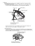
Reviews: