background image

62

CONNECTING THE INTERFACE CABLE

This unit includes both USB and parallel interface connectors.
Interface cables for connecting the unit to your computer are not included with this 
unit. Please purchase the appropriate cable for your computer.

Interface cable

Parallel interface cable

IEEE 1284-Shielded type bi-directional parallel interface cable (2 m (6 feet) Max.)

USB interface cable

Shielded twisted pair cable, high-speed transmission equivalent (2 m (6 feet) Max.)

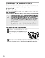
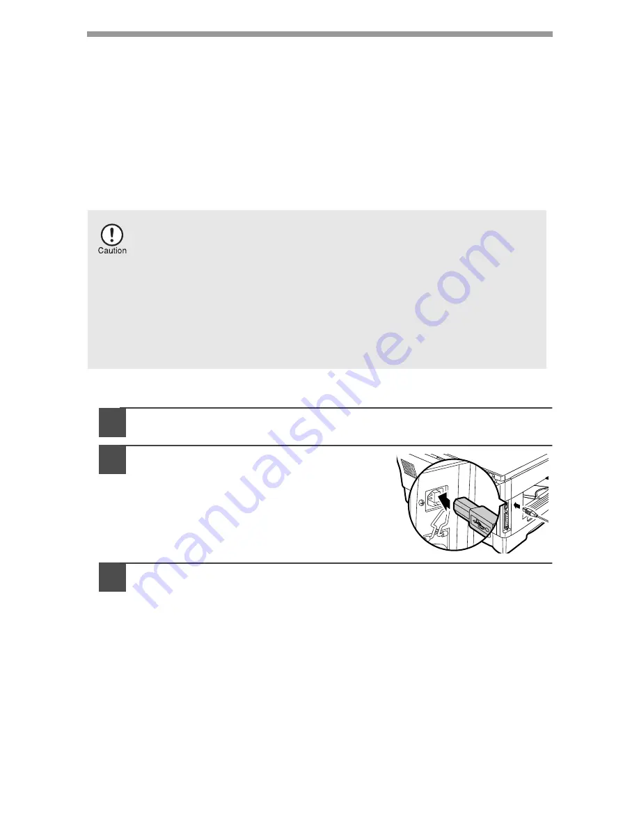
Connecting the USB interface cable

1

Obtain a shielded USB interface cable.

2

Insert the cable into the USB interface 
connector located on the rear of the 
unit.

3

Insert the other end of the cable into the interface connector of 
your computer, or the USB hub connected to your computer.

If you intend to use the unit as a scanner, it must be connected to 
your computer with a USB interface cable. The scanner function 
cannot be used if the unit is connected with a parallel cable.

USB is available with a PC/AT compatible computer that was originally 
equipped with USB and had Windows 98, Windows Me, Windows 
2000 Professional, Windows XP Professional or Windows XP Home 
Edition preinstalled.

Do not connect the interface cable before installing the MFP driver. 
The interface cable should be connected during installation of the 
MFP driver. (p.38)

Summary of Contents for e-studio120

Page 1: ......

Page 2: ...s or accidents beyond the reasonable control of TOSHIBA TEC CORPORATION including without limitation acts of God war riot civil commotion malicious or deliberate damage fire flood or storm natural calamity earthquakes abnormal voltage or other disasters c additions modifications disassembly transportation or repairs by any person other than service technicians authorized by TOSHIBA TEC CORPORATION...

Page 3: ...lowing measures Reorient or relocate the receiving antenna Increase the separation between the equipment and receiver Connect the equipment into an outlet on a circuit different from that to which the receiver is connected Consult the dealer or an experienced radio TV technician for help WARNING Changes or modification mode to this equipment not expressly approved by Toshiba TEC or parties authori...

Page 4: ... ventilation as the copier emits a small amount of ozone A small amount of ozone is produced within the unit during operation The emission level is insufficient to cause any health hazard Note The present recommended long term exposure limit for ozone is 0 1ppm 0 2mg m3 calculated as an 8hr time weighted average concentration However since the small amount that is emitted may have an objectionable...

Page 5: ... JA SUOJALUKITUS OHITETTAESSA OLET ALTTIINA NÄKYMÄTÖNTÄ LASERSÄTEILYLLE ÄLÄ KATSO SÄTEESEEN Laserstrahl CLASS 1 LASER PRODUCT LASER KLASSE 1 LUOKAN 1 LASERLAITE KLASS 1 LASERAPPARAT VAROITUS LAITTEEN KÄYTTÄMINEN MUULLA KUIN TÄSSÄ KÄYTTÖOHJEESSA MAINITULLA TAVALLA SAATTAA ALTISTAA KÄYTTÄJÄN TURVALLISUUSLUOKAN 1 YLITTÄVÄLLE NÄKYMÄTTÖMÄLLE LASERSÄTEILYLLE VARNING OM APPARATEN ANVÄNDS PÅ ANNAT SÄTT ÄN...

Page 6: ... In some areas the POWER switch positions are marked I and on the copier instead of ON and OFF The symbol denotes the copier is not completely de energized but in a stand by condition at this POWER switch position If your copier is so marked please read I for ON and for OFF Caution For a complete electrical disconnection pull out the main plug The socket outlet shall be installed near the equipmen...

Page 7: ...adjustments or performance of procedures other than those specified herein may result in hazardous radiation exposure The socket outlet should be installed near the equipment and be easily accessible The power plug should be unplugged from the outlet once a year or more often to clean the area between its edges If dust collects in the power plug area humidity or the like may cause the insulation t...

Page 8: ...get damp resulting in paper misfeeds Trademark acknowledgements Microsoft and Windows are trademarks of Microsoft Corporation in the U S A and other countries IBM and PC AT are trademarks of International Business Machines Corporation Adobe and Acrobat are trademarks of Adobe Systems Incorporated All other trademarks and copyrights are the property of their respective owners Wave length 770 nm 795...

Page 9: ... NUMBER OF COPIES 23 5 MAINTENANCE TONER CARTRIDGE REPLACEMENT 24 CLEANING THE UNIT 27 6 TROUBLESHOOTING THE UNIT TROUBLESHOOTING 29 STATUS INDICATORS 30 MISFEED REMOVAL 31 DEVELOPER REQUIRED 34 MAINTENANCE REQUIRED 34 7 INSTALLING THE SOFTWARE SOFTWARE FOR THE TOSHIBA PERSONAL MFP SERIES 35 HARDWARE AND SOFTWARE REQUIREMENTS 36 BEFORE INSTALLATION 36 INSTALLING THE SOFTWARE 38 INDICATORS ON THE O...

Page 10: ...mation pertinent to the use of the unit When references are made to paper sizes and weights the inch series values are quoted in brackets For example Page 7 56g m2 to 80g m2 15 lbs to 21 lbs A4 8 1 2 x 11 Warns the user that injury may result if the contents of the warning are not properly followed Cautions the user that damage to the unit or one of its components may result if the contents of the...

Page 11: ...e drum 3 14 15 16 5 Original table Operation panel Front cover Paper tray Side cover Side cover open button Multi bypass tray Bypass tray guides Paper output tray Paper output tray extension 1 2 3 4 5 6 7 8 9 10 Power switch Handle Power cord Fusing unit release lever Transfer charger Charger cleaner 11 12 13 14 15 16 ...

Page 12: ...O Selected mode is shown by a lit indicator p 17 Power save indicator Lights up when the unit is in a power save mode p 21 p 22 1 2 3 4 5 6 7 8 9 10 ZOOM keys and indicator Use to select any reduction or enlargement copy ratio from 25 to 400 in 1 increments p 19 Copy quantity keys Use to select the desired copy quantity 1 to 99 p 17 Use to make user program entries p 22 Tray select key Use to sele...

Page 13: ...Special papers such as transparency film labels and envelope must be fed one sheet at a time through the bypass tray Type of paper feeding Type of media Size Weight Paper tray Standard paper A4 210mm x 297mm A5 148 5mm x 210mm B5 182mm x 257mm Letter x 11 Legal 8 1 2 x 14 Invoice 5 1 2 x 8 1 2 56g m2 to 80g m2 15 lbs to 21 lbs Bypass tray Standard paper and thick paper A4 210mm x 297mm A5 148 5mm ...

Page 14: ... stored out of the wrapper or in packages standing on end may curl or get damp resulting in paper misfeeds Be sure to use only genuine TOSHIBA parts and supplies For best copying results be sure to use only TOSHIBA Genuine Supplies which are designed engineered and tested to maximize the life and performance of TOSHIBA copiers Look for the Genuine Supplies label on the toner package ...

Page 15: ...nd length Squeeze the lever of paper guide and slide the guide to match with the width of the paper Move paper guide to the appropriate slot as marked on the tray 3 Fan the paper and insert it into the tray Make sure the edges go under the corner hooks Do not load paper above the maximum height line Exceeding the line will cause a paper misfeed A B Paper guide B Paper guide A ...

Page 16: ...he paper and the guide and check if the guide is not set too narrow causing the paper to bend Loading paper in these ways will result in document skew or a paper jam When not using the unit for an extended period remove all paper from the paper tray and store it in a dry place If paper is left in the unit for an extended period the paper will absorb moisture from the air resulting in paper jams Wh...

Page 17: ...from 104 to 128g m2 28 to 34 5 Ibs A4 8 1 2 X 11 is the maximum size 1 Place the original face down on the original table Align it with the original scale and close the original cover 2 Open the bypass tray and extend the tray The original image must be smaller than the paper or media for copying If the original image is bigger than the paper or media this may cause smudges on the edges of the cop...

Page 18: ...ray Set the number of copies if using standard copy paper Press the start key Paper must be fed narrow side into the feed slot Transparency film labels and other special purpose papers must be fed individually When copying onto transparency film remove each copy promptly Do not let copies stack up When loading an envelope make sure that it is straight and flat Print face ...

Page 19: ...the paper size p 7 If paper is not loaded see page 9 If you are using the bypass tray check the paper size and then proceed to the next step without loading paper 2 Turn on the unit p 14 3 Place the original If you are using the original table see ORIGINAL PLACEMENT p 16 If you are using the ADF see Using the ADF p 67 When copying onto paper larger than A4 8 1 2 x 11 size pull out the paper output...

Page 20: ...ther than the country where the unit was purchased you will need to make sure that your local power supply is compatible with your model If you plug the unit into an incompatible power supply irreparable damage to the unit will result Only insert the power cord into a properly grounded wall socket Do not use extension cords or power strips The unit will enter a power save mode once the set time ha...

Page 21: ...tings when the time set with the Auto clear time setting p 21 elapses after a copy or scanner job is finished or when the clear key is pressed twice The initial settings of the operation panel are shown below When copying is begun in this state the settings in the following table are used Power off methods If not used for a certain period of time the unit will automatically enter auto power shut o...

Page 22: ...iginal cover straight up 2 To reattach the original cover reverse the above procedure 3 The original table can read up to A4 8 1 2 x 14 original Image loss 4mm 5 32 can occur at the leading and trailing edges of the copies Also image loss 4 5mm 11 64 in total can occur along the other edges of the copies When copying a book or an original which has been folded or a crumpled original press down the...

Page 23: ...DJUSTMENT PHOTO COPYING Exposure adjustment Copy density adjustment is not required for most originals in the automatic exposure mode To adjust the copy density manually or to copy photographs the exposure level can be adjusted in five steps manually 1 Press the exposure mode selector key to select the MANUAL mode or PHOTO mode 2 Use the light and dark keys to adjust the exposure level If exposure...

Page 24: ...nd dark indicators corresponding to the automatic exposure level which has been selected will light up 3 Press the light or dark key to lighten or darken the automatic exposure level as desired If exposure level 2 is selected the two left handmost indicators for that level will light up simultaneously Also if level 4 is selected the two right handmost indicators for that level will light up simult...

Page 25: ...and 400 To select a zoom ratio When a ZOOM or key is pressed the ZOOM indicator will light up and the zoom ratio will be displayed in the display To verify a zoom setting without changing the zoom ratio press and hold down the copy ratio display key When the key is released the display will return to the copy quantity display To reset the ratio to 100 press the copy ratio selector key repeatedly u...

Page 26: ...TING THE TRAY 1 Press the tray select key Each time you press the tray select key the location indicated by the paper feed location indicator changes in the following order paper tray 1 paper tray 2 bypass tray ...

Page 27: ...unit enters the auto power shut off mode the power save indicator will light up and other indicators except the ONLINE indicator will go out The auto power shut off mode saves more power than the preheat mode but requires a longer time before starting copying To copy from the auto power shut off mode press the start key Then make desired copier selections and press the start key using the normal c...

Page 28: ...rs of certain functions to be set changed or canceled as desired Setting the power save modes auto clear time stream feeding mode and resolution of AUTO MANUAL mode 1 Press and hold down the light and dark keys simultaneously for more than 5 seconds until all the alarm indicators blink and appears in the display 2 Use the copy quantity key to select a user program number 1 auto clear time 2 prehea...

Page 29: ... copies 1 Press the clear key to reset the display to zero 2 Press and hold down the clear key for approximately 5 seconds The total number of copies will appear in two steps each with three digits Example Total number of copies is 1 234 Program No Mode Parameters 1 Auto clear time 0 OFF 1 10sec 2 30sec 3 60sec 4 90sec 5 120sec 2 Preheat mode 0 30sec 1 60sec 2 90sec 3 Auto power shut off timer 0 2...

Page 30: ... and then open the side cover while pressing the side cover open button 2 Push gently on both sides of the front cover to open the cover Be sure to use only genuine TOSHIBA parts and supplies For best copying results be sure to use only TOSHIBA Genuine Supplies which are designed engineered and tested to maximise the life and performance of TOSHIBA copiers Look for the Genuine Supplies label on th...

Page 31: ...r out of the toner cartridge as shown in the illustration Discard the shutter After removing the toner cartridge do not shake it or tap on it Doing so may cause toner to leak from the cartridge Put the old cartridge immediately in the bag contained in the box of the new cartridge Dispose of the old toner cartridge in accordance with local regulations Grasp the toner cartridge as shown in the illus...

Page 32: ... close the front cover securely and then close the side cover If the covers are closed in the wrong order the covers may be damaged Even after a new toner cartridge is installed the start indicator may not light up indicating copying cannot be restarted toner is not sufficiently fed In this case open and close the side cover The copier will feed toner again approximately 2 minutes and then copying...

Page 33: ... the original cover Stains on the glass or cover will also be copied Wipe the glass and cover with a soft clean cloth If necessary dampen the cloth with a glass cleaner Before cleaning be sure to turn the power switch off and remove the power cord from the outlet Do not use thinner benzene or other volatile cleaning agents Doing so may cause deformation discoloration deterioration or malfunction O...

Page 34: ...holding the tab Set the charger cleaner onto the right end of the transfer charger gently slide the cleaner to the left end and then remove it Repeat this operation two or three times 4 Return the charger cleaner to its original position Close the side cover by pressing the round projections near the side cover open button 5 Turn the power switch on p 14 Slide the charger cleaner from the right en...

Page 35: ...t in the photo exposure mode Cancel the photo exposure mode 17 Dust dirt smudges appear on copies Original table or original cover dirty Clean regularly 27 Original smudged or blotchy Use a clean original Striped copies Is transfer charger clean Clean the transfer charger 28 Paper misfeeds frequently Non standard paper used Use standard paper If using special papers feed the paper through the sing...

Page 36: ...quired 34 Power save indicator is steadily lit The unit is in the preheat mode Press any key to cancel the preheat mode 21 The unit is in the auto power shut off mode Press the start key to cancel the auto power shut off mode 21 The paper tray indicator is blinking The paper tray is not installed properly Push the tray into the unit securely CH is blinking in the display The toner cartridge is not...

Page 37: ...ed location Remove the misfed paper following the instructions for each location in the illustration below If the misfeed indicator blinks proceed to A Misfeed in the paper feed area p 32 If paper is misfed here proceed to A Misfeed in the paper feed area p 32 If paper is misfed here proceed to B Misfeed in the fusing area p 32 If the misfed paper is seen from this side proceed to C Misfeed in the...

Page 38: ...pen button The misfeed indicator will go out and the start indicator will light up B Misfeed in the fusing area 1 Lower the fusing unit release lever The fusing unit is hot Do not touch the fusing unit when removing misfed paper Doing so may cause a burn or other injury Do not touch the photoconductive drum green portion when removing the misfed paper Doing so may cause smudges on copies If the pa...

Page 39: ...er See B Misfeed in the fusing area p 32 2 Open the front cover To open the front cover see TONER CARTRIDGE REPLACEMENT p 24 3 Rotate the feeding roller in the direction of the arrow and gently remove the misfed paper from the exit area The fusing unit is hot Do not touch the fusing unit when removing misfed paper Doing so may cause a burn or other injury Do not touch the photoconductive drum gree...

Page 40: ...s up the developer should be replaced DEVELOPER REPLACEMENT SHOULD ONLY BE DONE BY AN AUTHORIZED TOSHIBA SERVICE TECHNICIAN Contact your service center as soon as possible MAINTENANCE REQUIRED When maintenance indicator lights up service by an authorized TOSHIBA service technician is required Contact your service center as soon as possible When closing the covers be sure to close the front cover s...

Page 41: ...this unit with TWAIN compliant and WIA compliant application Printer driver Enables you to use the printer function of this unit with your computer Print Status Window The print state and information on current printing are displayed on the status monitor window Desktop Document Manager An integrated software environment that makes it easy to manage document and image files and launch applications...

Page 42: ...t s scanner function cannot be used Computer type IBM PC AT or compatible computer equipped with a USB1 1 1 or bi directional parallel interface IEEE 1284 Operating system 2 Windows 95 Windows 98 Windows Me Windows NT Workstation 4 0 ServicePack 5 or later 3 Windows 2000 Professional 3 Windows XP Professional 3 Windows XP Home Edition 3 Display 800 x 600dots SVGA display with 256 colors or better ...

Page 43: ...interface p 42 Parallel Installing onto Windows 95 98 Me NT4 0 2000 Parallel interface p 45 Windows Me USB Installing onto Windows 98 Me 2000 USB interface p 42 Parallel Installing onto Windows 95 98 Me NT4 0 2000 Parallel interface p 45 Windows 2000 USB Installing onto Windows 98 Me 2000 USB interface p 42 Parallel Installing onto Windows 95 98 Me NT4 0 2000 Parallel interface p 45 Windows 95 NT ...

Page 44: ... For this description it is assumed that the mouse is configured for right hand operation To print or scan the MFP must be in the online state The scanner feature only works when using a USB interface cable If any error message appears solve the problem following the instructions on the screen After your problem is solved the installing procedure will be continued Depending on your problem you may...

Page 45: ...ble is not connected and click the Next button 3 Click the Next button in the dialog box to install the MFP driver or Cancel to quit the installation The setup program will start to copy the files If the following screen appears while the files are being copied the message may appear more than once click Continue Anyway 4 When the The MFP driver installation is complete dialog box appears click th...

Page 46: ...start 8 Begin installation of the Desktop Document Manager This step will start if it was selected in step 4 1 After confirming the message in the Welcome to Desktop Document Manager installation window click the Next button 2 Read the message in the Information window and then click the Next button 3 When the Choose Destination Location window appears click the Next button 4 When the Select Progr...

Page 47: ...ardware dialog box will appear Click the Continue Anyway button 3 When installation of the driver is completed click the Finish button to finish the scanner driver installation 12 Begin installation of the printer driver 1 TOSHIBA e STUDIOnnn where nnn is the model name of your MFP will appear in the Found New Hardware Wizard dialog box Select Install the software automatically Recommended and cli...

Page 48: ...are packages to be installed on the screen and then click the Start button The software packages to be installed will be displayed on the screen If inappropriate packages are displayed click the Back button to select appropriate packages again When any of Hardware Found or Found New Hardware Wizard messages appear during the software installation be sure to click the Cancel button If the language ...

Page 49: ...ot using a parallel interface cable for connection to the MFP please click the No button 5 When the The MFP driver installation is complete dialog box appears click the OK button The Button Manager installer will start 7 Begin installation of the Button Manager This step will start if it was selected in step 4 1 After confirming the message in the Welcome window click the Next button 2 Read the me...

Page 50: ...answer the question to continue the Desktop Document Manager installation 5 Click the Finish button when the message to inform you of the completion of the installation appears 9 Click the Close button when the message to inform you of the completion of the installation appears When the Now connect the MFP interface cable to the PC dialog box or After Windows system restart dialog box appears clic...

Page 51: ...t connected and click OK 6 Check the contents of the package on the screen and then click the Start button The software packages to be installed will be displayed on the screen If inappropriate packages are displayed click the Back button to select only appropriate software packages When any of Hardware Found or Found New Hardware Wizard messages appear during the software installation be sure to ...

Page 52: ...odel screen will appear Select the model number that is the same as the model name of your MFP and click the Next button Be sure to select the displayed model number that is the same as the MFP s model name If they are not the same the driver will not be installed correctly 5 Establish the printer settings and click the Next button Select LPT1 for the port to be used If LPT1 does not appear it is ...

Page 53: ...o install Desktop Document Manager imaging which does not support LZW compression appears answer the question to continue the Desktop Document Manager installation 5 Click the Finish button when the message to inform you of the completion of the installation appears 9 Click the Close button when the message to inform you of the completion of the installation appears 10 When the Now connect the MFP...

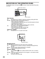
Page 54: ...ituations During copying or scanning The unit is in the auto power shut off mode When a misfeed or error has occurred Power save indicator On Indicates the unit is in a power save mode ONLINE indicator The ONLINE key is pressed and on line and off line are changed On Indicates the unit is ready for printing or scanning is being performed On line Blinking Printing or data is being received from a c...

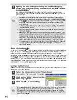
Page 55: ... copy paper See LOADING PAPER p 7 2 Open the document you intend to print and select Print from the application s File menu 3 Make sure that TOSHIBA e STUDIOnnn where nnn is the model name of your unit are selected as the current printer If you intend to change any print setting click the Preferences button to open the setting dialog On Windows 95 98 Me NT 4 0 click the Properties button On Window...

Page 56: ...ile and select Properties 2 Click on the Utility tab and set the Input Tray Options 3 Click on OK to save setting If copying is being performed when printing is started copying will continue After copying is complete printing will be executed when the clear key is pressed twice the ONLINE key is pressed to switch the unit to the online state or approximately 60 seconds auto clear time elapse The a...

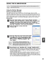
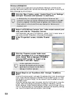
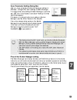
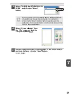
Page 57: ...the Select an event button and select ScanMenu SC1 from the pull down menu Select Button Manager TOSHIBA Personal MFP series in Start this program and click Apply 4 Repeat Step3 to set ScanMenu SC2 through ScanMenu SC6 Click the Select an event button and select ScanMenu SC2 from the pull down menu Select Button Manager TOSHIBA Personal MFP series in Start this program and click Apply Do the same ...

Page 58: ...SC2 through ScanMenu SC6 Click the Scanner events and select ScanMenu SC2 from the pull down menu Select Button Manager TOSHIBA Personal MFP series in Start this program and click Apply Do the same for each ScanMenu through ScanMenu SC6 When the settings have been completed click the OK button to close the screen When the settings have been completed in Windows start the Button Manager Adjust deta...

Page 59: ...f your unit series device event and start your selected application according to the scan setting made on the e STUDIOnnn where nnn is the model name of your unit operation panel SC1 SC2 SC3 SC4 SC5 SC6 This will scan directly into your application from the device This dialog shows the SC1 event set to go directly to Button Manager With the Button Manager set to send the image to Desktop Document ...

Page 60: ...Windows Me Windows 2000 and Windows XP Windows Platforms provide a mechanism for software to handle external events for a scanner device like the TOSHIBA e STUDIOnnn where nnn is the model name of your unit series products This mechanism is controlled by the device manager on a device basis Applications that can handle events from a scanner camera device register with the Windows Event Manager and...

Page 61: ...e application numbers are initially as follows Scanning is not possible during a copy job If the unit is used to begin a scan job during a print job the scan job will be stored and scanning will begin when the print job is completed Application number Application launched SC1 Desktop Document Manager if installed SC2 E mail your standard e mail program in the Windows OS you are using SC3 Fax if a ...

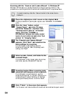
Page 62: ...omputer Follow the steps below to open the scanner driver setup screen As an example this instruction is given using Desktop Document Manager as an image capture application Using the TOSHIBA TWAIN 1 Place the original you wish to scan on the original table For the procedure for placing the original see ORIGINAL PLACEMENT p 16 2 After starting Desktop Document Manager click the File menu and selec...

Page 63: ...for scanning refer to the online manual and help file and click the Scan button Scan is started If you use more than one scanning device select the scanner you want to use through the application The method for accessing the Select Scanner option depends upon the application For more information see the online manual or the help file of your application Click here ...

Page 64: ...ing Tasks 3 The Scanner and Camera Wizard appears Click Next and establish the basic settings for scanning For information on the settings see the Windows XP help file After completing each setting click Next 4 Select a name format and folder for the scanned image For information on the image name file format and folder see the Windows XP help file 5 Scanning begins When scanning ends select the n...

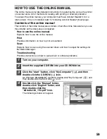
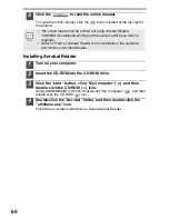
Page 65: ...s completed How to use the online manual Explains how to use the online manual Print Provides information on how to print a document Scan Explains how to scan using the scanner driver and how to adjust the settings for the Button Manager Troubleshooting Provides instructions on how to solve driver or software problems 1 Turn on your computer 2 Insert the supplied CD ROM into your CD ROM drive 3 Cl...

Page 66: ...lick the CD ROM icon Windows95 98 Me NT4 0 2000 double click My Computer and then double click the CD ROM icon 4 Double click the Acrobat folder and then double click the ar500enu exe icon Follow the on screen instructions to install Acrobat Reader The online manual can be printed out using Acrobat Reader TOSHIBA recommends printing out the sections which you refer to regularly Refer to Help of Ac...

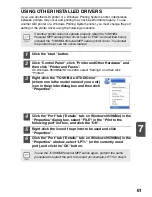
Page 67: ...it icon in the printer dialog box and then click Properties 4 Click the Port tab Details tab on Windows 95 98 Me in the Properties dialog box select FILE in the Print to the following port list box and click the OK 5 Right click the icon of the printer to be used and click Properties 6 Click the Port tab Details tab on Windows 95 98 Me in the Properties window select LPT1 or the currently used por...

Page 68: ...he cable into the USB interface connector located on the rear of the unit 3 Insert the other end of the cable into the interface connector of your computer or the USB hub connected to your computer If you intend to use the unit as a scanner it must be connected to your computer with a USB interface cable The scanner function cannot be used if the unit is connected with a parallel cable USB is avai...

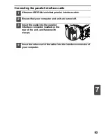
Page 69: ...ed parallel interface cable 2 Ensure that your computer and unit are turned off 3 Insert the cable into the parallel interface connector located on the rear of the unit and fasten with clasps 4 Insert the other end of the cable into the interface connector of your computer ...

Page 70: ...y ratio Variable 25 to 400 in 1 increments total 376 steps Fixed 25 70 86 100 141 400 25 64 78 100 129 400 Exposure system Moving optical source slit exposure stationary platen with automatic exposure Fusing system Heat rollers Development system Magnetic brush development Light source Cold cathode fluorescent lamp Resolution 600 x 300dpi Auto Manual mode 600 x 600dpi Photo mode Gradation 2 levels...

Page 71: ...mg m3 Optional equipment Auto document feeder MR 2014 250 sheet paper feed unit MY 1019 Printing system Dry electrostatic transfer Printing size A6 to A4 3 1 2 x 5 1 2 to 8 1 2 x 14 1 Print speed Max 12 pages min Letter or A4 Continuous printing Max 99 pages subtractive counter First print time Approximately 9 6 seconds Paper A4 2 Resolution Printer 600 dpi Scanner 600 x 1200 dpi Emulation TOSHIBA...

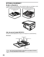
Page 72: ...ns include the following Auto document feeder MR 2014 The auto document feeder ADF holds up to 30 originals for automatic feeding Part names ADF Auto Document Feeder is called SPF in the software included in the CD ROM packed with the machine Auto document feeder MR 2014 250 sheet paper feed unit MY 1019 Document feeder tray Feeding roller cover Original guides ADF exit area ...

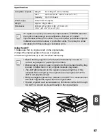
Page 73: ... notice The performance specification figures indicated are nominal values of production units There may be some deviations from these values in individual units Before feeding originals in the document feeder tray be sure to remove any staples or paper clips from them Before placing curled or wavy originals into the document feeding tray be sure to flatten them If not original misfeeds may result...

Page 74: ...n the ADF An original misfeed may occur at one of three locations if the misfed original is seen from the document feeder tray A in the document feeder tray if the misfed original is not seen from the document feeder tray B in the exit area or C under the feeding roller Remove the misfed original following the instructions for each location A Open the feeding roller cover and pull the original gen...

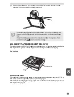
Page 75: ...names Loading copy paper The method of loading copy paper for the paper tray of the paper feed unit PFU is the same as for the paper tray in the copier See page 7 The method of changing the copy paper size is also the same for the paper tray in the copier See page 9 A number may appear in the display after a minus sign indicating the number of the originals that must be returned to the document fe...

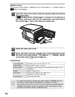
Page 76: ...indicator will go out and the start key will light up Specifications Copy paper size A5 to A4 5 1 2 x 8 1 2 to 8 1 2 x 14 Paper weight 56 to 80 g m2 15 lbs to 21 lbs Paper capacity One paper tray with capacity for 250 sheets of 80 g m2 21 lb bond paper Weight Approx 3 kg 6 6 lbs Dimensions 498 mm W x 395 mm D x 88 mm H 19 6 W x 15 6 D x 3 5 H Power supply Drawn from the copier As a part of our pol...

Page 77: ...d in the manual 4 Copy flow 13 Copy quantity 17 Copy quantity key 6 17 22 Copy ratio display key 6 19 Copy ratio selector indicator 6 19 Copy ratio selector key 6 19 D Dark key 6 18 Developer replacement required indicator 6 30 34 Desktop Document Manager 35 Developer required 34 Display 6 Displaying total number of copies 23 E Exposure adjustment 17 Exposure mode indicator 6 17 Exposure mode sele...

Page 78: ...r cord socket 5 Power off 15 POWER ON 14 Power save indicator 6 48 Power switch 5 14 Preheat mode 22 Proper storage 2 R Reduction enlargement zoom 19 S Scanner driver 35 Scanner indicator 6 48 SCANNER key 6 55 Scanning from your computer 56 Scanning with the Scanner and Camera Wizard 58 Side cover 5 Side cover open button 5 Software for the TOSHIBA Personal MFP series 35 Specifications 64 Start in...

Page 79: ...Loading paper Paper tray 9 Bypass 11 Loading the original 16 Opening the printer driver 49 Power off 15 POWER ON 14 Printing 49 Removing paper jams Fusing area 32 Paper feed area 32 Transport area 33 Replacing the toner cartridge 24 Scanning Button Manager 51 Scanner and Camera Wizard 58 TOSHIBA TWAIN 56 Setting the copy quality AUTO 18 MANUAL 17 PHOTO 18 Setting the copy quantity 17 Setting the t...

Page 80: ...puter to another or over a network 3 Termination This license is effective until terminated You may terminate this License at any time by destroying the Software and related documentation and all copies thereof This License will terminate immediately without notice from TOSHIBA TEC and or TOSHIBA TEC S Licensors if you fail to comply with any provision of this License Upon termination you must des...

Page 81: ...SE NO ORAL OR WRITTEN INFORMATION OR ADVICE GIVEN BY TOSHIBA TEC OR A TOSHIBA TEC AUTHORIZED REPRESENTATIVE SHALL CREATE A WARRANTY OR IN ANY WAY INCREASE THE SCOPE OF THIS WARRANTY SHOULD THE SOFTWARE PROVE DEFECTIVE YOU AND NOT TOSHIBA TEC OR A TOSHIBA TEC AUTHORIZED REPRESENTATIVE ASSUME THE ENTIRE COST OF ALL NECESSARY SERVICING REPAIR OR CORRECTION SOME JURISDICTIONS DO NOT ALLOW THE EXCLUSIO...

Page 82: ...MEMO ...

Page 83: ...F ...

Page 84: ...R02062019202 TTEC Ver03 2006 11 TINSE0816QSZ2 2 17 2 HIGASHIGOTANDA SHINAGAWA KU TOKYO 141 8664 JAPAN ...

Reviews: