No.
18
Item
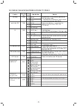
Louver control
(Continued):
Outline of specifications
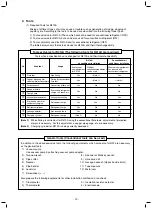
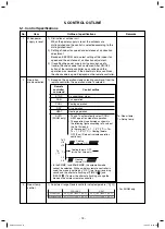
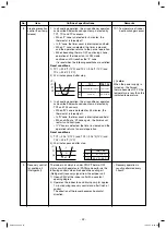
<<Selection of Swing mode>>
• For the Swing mode, the following three types of modes
are selectable and settable by keeping Swing/Direction
SWING/FIX
button pushed for 4 seconds or more on the remote
controller.
1) Standard (4 pieces: same phase) swing
→
Data: [0001 (At shipment)]
When Swing operation is selected, four louvers align at
the horizontal discharge position and then start the
Swing operation at the same time.
2) Dual swing
→
Data: [0002]
When operation is selected, the louvers of louver No.
[01] and [03] move to the horizontal discharge position,
the louvers of louver No. [02] and [04] move to the
downward discharge position and then start the Swing
operation at the same time.
3) Cycle swing
→
Data: [0003]
When operation is selected, the louver No. [01] moves to
the horizontal discharge position, [03] to the downward
discharge position, [02] and [04] to the middle position
and then start the Swing operation at the same time.
• Three types of the swing modes can be also selected
and set by the setup data of Item code (DN) [F0].
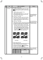
• In case of selecting the Swing mode, “Dual swing” or
“Cycle swing”, the following numerals is displayed at
the center of the remote controller screen for approx.
3 seconds when
SWING/FIX
button was pushed to select
[SWING]. (No display for the standard swing)
Remarks
Carry out setting operation
during stop of the unit;
otherwise the unit stops
operation.
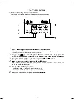
For the setting operation,
refer to [How to set up type
of the swings] in Item
“
Dual swing
Cycle swing
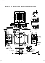
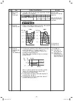
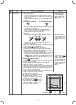
<<Louver lock (Louver fix)>>
• For the air direction setup for each discharge port, the louver
position can be locked during the normal operation.
• An arbitrary air direction of an arbitrary louver can be
registered and set by keeping
UNIT
LOUVER
button pushed for
4 seconds or more on the remote controller.
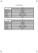
• The louver lock can be set by registering the setup data to
Item code (DN) [F1] to [F4] according to the following table.
Carry out setting operation
during stop of the unit;
otherwise the unit stops
operation.
Alternate lighting
(0.5 sec.)
Alternate lighting
(0.5 sec.)
F1
F2
F3
F4
Objective louver No.
01
02
03
04
Setup data
0000: Release (At shipment)
0001: Horizontal discharge position
~
0005: Downward discharge position
7 APPLIED CONTROL”
CODE No.
- 26 -
Summary of Contents for Carrier MMU-AP0074HPUL
Page 15: ...2 WIRING DIAGRAM 15 ...

