No.
3
4
5
Item
Room temp.
control
(Continued)
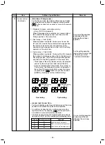
Outline of specifications
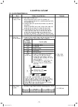
2) Using the CODE N . 06, the setup temperature in heating
operation can be corrected.
Remarks
Shift of suction
temperature in heating
operation
Except while sensor of
the remote controller is
controlled
Setting at shipment
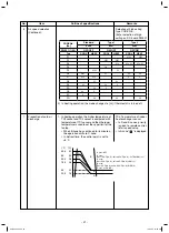
1) Based on the difference between Ta and Ts, the opera
tion
capacity is determined by the outdoor unit.
Setup data
Setup temp. correction
0
2
4
6
+0°C
+2°C
(+3.6°F)
+4°C
(+7.2°F)
+6°C
(+10.8°F)
Setup data
2
Automatic
capacity control
Automatic
cooling/heating
control
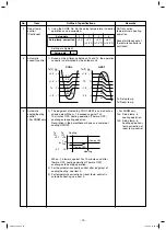
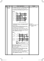
1) The judgment of selecting COOL/HEAT is carried out as
shown below. When +1.5 exceeds against Tsh
10 minutes OFF, heating operation (Thermo. OFF)
exchanges to cooling operation.
Description in the parentheses shows an example of
cooling ON/OFF.
When –1.5 lowers against Tsc 10 minutes and after
thermo. OFF, cooling operation (Thermo. OFF)
exchanges to heating operation.
2) For the automatic capacity control after judgment of
cooling/heating, see Item 4.
3) For temperature correction of room temp. control in
automatic heating, see Item 3.
Ts: Setup temp.
Ta: Room temp.
∗
For SHRM only
Tsc: Setup temp. in
cooling operation
Tsh: Setup temp. in
heating ope
temp. correction of
room temp. control
Ta
(°C)
-1.5
Tsc
Tsh
+1.5
Heating
(Cooling OFF)
(Cooling ON)
or
Cooling
Ta
(°C)
+2
Ta
(°C)
+1
+1
Ts
Ts
–1
–1
–2
COOL
HEAT
S3
S5
S7
S9
SB
SD
SF
S0
SD
SB
S9
S7
S5
S3
S0
∗
For SHRM only
o
SVM-13085.indb 22
SVM-13085.indb 22
12/24/13 10:56 AM
12/24/13 10:56 AM
Ta
(°F)
+
3.6
+
1.8
Ts
–
1.8
Ta
(°F)
+
1.8
TS
-1.8
–
3.6
Ta
(°
F
)
-
2.7
+
2.7
- 19 -
Summary of Contents for Carrier MMU-AP0074HPUL
Page 15: ...2 WIRING DIAGRAM 15 ...


