– 4 –
GENERAL ADJUSTMENTS
SPECIFIC INFORMATIONS
WARNING
: BEFORE SERVICING THIS CHASSIS, READ THE “X-RAY RADIATION PRECAUTION”, “SAFETY PRECAU-
TION” AND “PRODUCT SAFETY NOTICE” ON PAGE 3 OF THIS MANUAL.
SET-UP ADJUSTMENT
■
The following adjustments should be made when a complete realignment is required or a new picture tube is installed.
Perform the adjustments in order as follows :
1. Color Purity
2. Convergence
3. White Balance
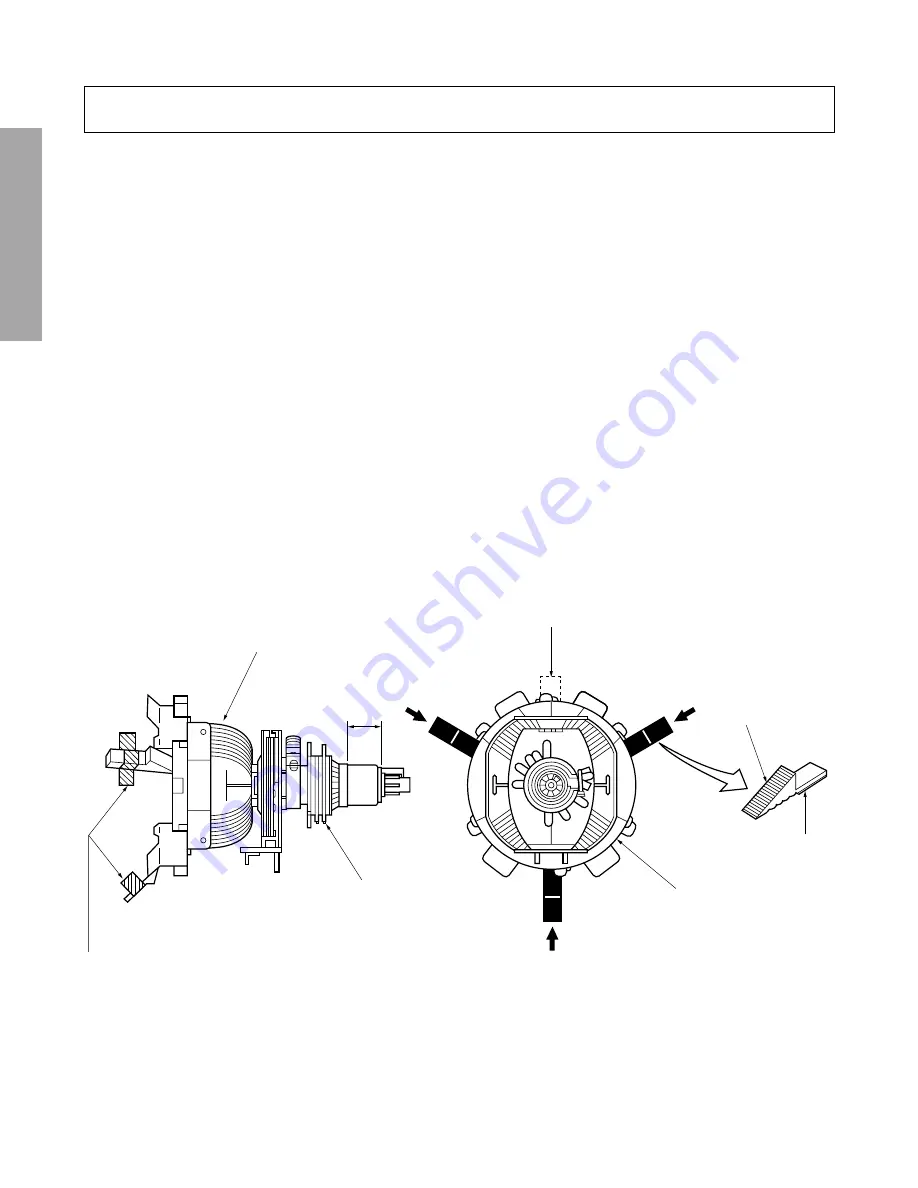
Note: The PURITY/CONVERGENCE MAGNET assembly and rubber wedges need mechanical positioning.
Refer to figure 1.
Mounting position of the purity magnet assembly should fit to same position as old one because slightly difference to
the position depend on a kind of tube.
*
There are no adjustment of purity and convergence in some picture tube (Unified with purity magnet)
GLASS CLOTH
TAPES
DEFLECTION
YOKE
TEMPORARY
MOUNTING
RUBBER WEDGE
ADHESIVE
DEFLECTION
YOKE
PURITY/
CONVERGENCE
MAGNET ASS'Y
29.1mm(28", 29")
25mm(25")
19mm(19", 20", 21")
14mm(13", 14")
Figure 1.
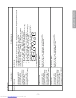
COLOR PURITY ADJUSTMENT
NOTE : Before attempting any purity adjustments, the receiver
should be operated for at least fifteen minutes.
1. Demagnetize the picture tube and cabinet using a degauss-
ing coil.
2. Set the brightness and contrast to maximum.
3. Use a green raster from among the built-in test signals.
4. Loosen the clamp screw holding the yoke and slide the
yoke backward or forward to provide vertical green belt
(zone) in the picture screen.
5. Remove the Rubber Wedges.
6. Rotate and spread the tabs of the purity magnet (See fig-
ure 2.) around the neck of the picture tube until the green
belt is in the center of the screen. At the same time, enter
the raster vertically.
7. Slowly move the yoke forward or backward until a uniform
green screen is obtained. Tighten the clamp screw of the
yoke temporarily.
8. Check the purity of the red and blue raster.
Summary of Contents for 32Z13B
Page 32: ... 32 SPECIFIC INFORMATIONS THIS PAGE IS INTENTIONALLY LEFT BLANK ...
Page 33: ... 33 34 SIGNAL BOARD PD0015C SIGNAL BOARD PD0015D BOTTOM FOIL SIDE ...
Page 34: ... 35 36 POWER DEF BOARD PD0016C POWER DEF BOARD PD0016D BOTTOM FOIL SIDE ...
Page 35: ... 37 38 CONT 1 BOARD PD0017A 1 BOTTOM FOIL SIDE CONT 2 BOARD PD0017A 2 BOTTOM FOIL SIDE ...
Page 37: ... 41 SPECIFIC INFORMATIONS MEMO ...
Page 38: ... 42 SPECIFIC INFORMATIONS MEMO ...
Page 40: ......


