background image

– 31 –

SPECIFIC INFORMATIONS

Location

Location

Location

Location

Location

Parts No.

Parts No.

Parts No.

Parts No.

Parts No.

Description

Description

Description

Description

Description

No.

No.

No.

No.

No.

Location

Location

Location

Location

Location

Parts No.

Parts No.

Parts No.

Parts No.

Parts No.

Description

Description

Description

Description

Description

No.

No.

No.

No.

No.

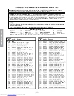
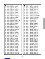
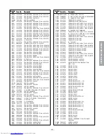
Z102

23303232

K9453M (32Z13G)

Z103

23107926

FILTER, TCF1012

Z103

23303189

FILTCF1114 (32Z13G)

Z104

23303072

CERAMIC FILTER, TCF1089

Z420

23144539

PROTECTOR, 491SERIES 125V 2A

Z891

23144543

PROTECTOR, 491SERIES 125V 5A

Z898

23144542

PROTECTOR, 491SERIES 125V 4A

Z902

23103839

CORE, FERRITE, TFE1012

ZP83

23144536

PROTECTOR, 491SERIES 125V 1A

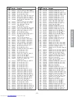
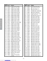
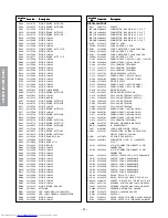
PC BOARD ASSEMBLIES

*

U901

23786507

PW UNIT CRT-D&DSM, PWU PD0014B

*

U902

23786508

PW UNIT SIGNAL, PWU PD0015C (32Z13B)

*

U902

23786640

PW UNIT SIGNAL, PWU PD0015D (32Z13G)

*

U903

23786509

PW UNIT POW&DEF, PWU PD0016C

(32Z13B)

*

U903

23786792

PW UNIT POW&DEF, PWU PD0016D

(32Z13G)

*

U904A 23786016

PW UNIT CONT-1, PWU PD0017A-1

*

U904B

23786017

PW UNIT CONT-2, PWU PD0017A-2

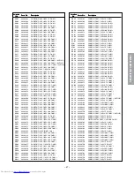
PICTURE TUBE

* V901

23312885

PICTURE TUBE, , 32W 50HZ FLAT

W76EJS011X107

TUNER

H001

23321413

TUNER, ALPS UK TEDB7-205A (32Z13B)

H001

23321370

TUNER, TN-EGA51L (32Z13G)

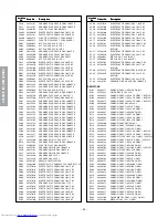
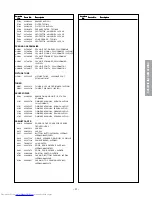
ACCESSORIES

K902

23306363

REMOCON HAND UNIT IR, CTVPAL

CT-90040

Y101

23565270

OWNER’S MANUAL, ENGLISH 28Z13B

32/28Z13B(ENG

Y101

23565287

OWNER’S MANUAL, ENGLISH 32Z13G

Y102

23565288

OWNER’S MANUAL, FRENCH 32Z13G

Y103

23565289

OWNER’S MANUAL, GERMAN 32Z13G

Y104

23565290

OWNER’S MANUAL, ITALIAN 32Z13G

Y105

23565291

OWNER’S MANUAL, SPANISH 32Z13G

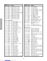
CABINET PARTS

A201S

23540689

COVER, FRONT COVER FOR SERVICE

FRONTCOVER S

A214

23035412

SCREW

A215

23035412

SCREW

A231

23445395

BUTTON, BUTTON(POWER) 32ZD08G

32ZD08G;B995158EP1

A236

23527188

GRILLE, SPEAKER GRILLE(L/R) 32 GRILLE

A238

23527130

PANEL(CENTRE), 32ZD06G

A241

70368125

PUSH CATCH

A242

23427819

DOOR, DOOR PROPER R 32ZD08G

32ZD08G;A995307EP1

A243

23427873

DOOR, DOOR PROPER L 28Z05B

A701

23064260

CARTON, CARTON 32Z07B

A702

23946038

PACKING, BOTTOM PACKING 32ZD08

32ZD08G;A995338E

A703

23946037

PACKING, TOP PACKING 32ZD08G

32ZD08G;A995337E

Summary of Contents for 32Z13B

Page 1: ...PRINTED IN JAPAN Jul 2001 T FILE NO 030 200112 SERVICE MANUAL COLOUR TELEVISION Z13B Chassis 32Z13B 32Z13G ...

Page 2: ...ENT 4 SERVICE MODE 6 DESIGN MODE 9 ELECTRICAL ADJUSTMENTS 10 CIRCUIT CHECK 17 CHAPTER 2 SPECIFIC INFORMATIONS SETTING ADJUSTING DATA 18 LOCATION OF CONTROLS 19 CIRCUIT BLOCK DIAGRAM 21 CHASSIS AND CABINET REPLACEMENT PARTS LIST 22 PC BOARDS BOTTOM VIEW 33 TERMINAL VIEW OF TRANSISTORS 40 SPECIFICATIONS 43 APPENDIX CIRCUIT DIAGRAM ...

Page 3: ... attempted by anyone unfamiliar with the necessary precautions on this receiver The following are the necessary precautions to be observed before servicing this chassis 1 An isolation transformer should be connected in the power line between the receiver and the AC line before any service is performed on the receiver 2 Always discharge the picture tube anode to the CRT conductive coating before ha...

Page 4: ...ECTION YOKE TEMPORARY MOUNTING RUBBER WEDGE ADHESIVE DEFLECTION YOKE PURITY CONVERGENCE MAGNET ASS Y 29 1mm 28 29 25mm 25 19mm 19 20 21 14mm 13 14 Figure 1 COLOR PURITY ADJUSTMENT NOTE Before attempting any purity adjustments the receiver should be operated for at least fifteen minutes 1 Demagnetize the picture tube and cabinet using a degauss ing coil 2 Set the brightness and contrast to maximum ...

Page 5: ...1 Do not remove cover paper on adhesive part of the wedge 3 Tilt front of the deflection yoke up or down to obtain better convergence in circumference See figure 3 Push the mounted wedge into the space between picture tube and the yoke to fix the yoke temporarily 4 Put other wedge into bottom space and remove the cover paper to stick 5 Tilt front of the yoke right or left to obtain better conver g...

Page 6: ...Remote Change of the data value Volume on TV or Remote Adjustment menu mode ON OFF MENU button on TV Initialization of the memory QA02 CALL Channel button on TV s Reset the count of operating protect circuit to 00 CALL Channel button on TV t RCUT selection 1 button GCUT selection 2 button BCUT selection 3 button CNTX or SCNT selection 4 button COLC selection 5 button TNTC selection 6 button Self d...

Page 7: ...llowing initialization is required 1 Enter the service mode then select any register item 2 Press and hold the CALL button on the Remote then press the CHANNEL s button on the TV The initialization of QA02 has been complated 3 Check the picture carefully If necessary adjust any adjustment item above Perform Auto search Memory on the owner s manual CAUTION Never attempt to initialize the data unles...

Page 8: ...3 Indicated color of mode now selected Green and Red Indicated color of other modes White Green Normal Red The microcomputer operates to provide judgement of no video signal The red color is still indicated though the signal is input failure may exist in input signal line including QV01 QV01 In case of indication green Normal In case of indication red with input signal Failure may exist in output ...

Page 9: ...ode changes the adjustment items in the order of table 3 s button for reverse order Refer to table 3 for data of design mode See SETTING ADJUSTING DATA on page 18 3 ADJUSTING THE DATA Pressing of VOLUME s or t button will change the value of data When QA02 is initialized items OPT0 OPT1 and OPT2 of DESIGN MODE are set to the data of the representative model of this chassis family Therefore because...

Page 10: ...before the difference between the belt of vertical retrace and the border of black portion of inside pattern is visible After that return vertical height and contrast ITEM ADJUSTMENT PROCEDURE Belt of vertical retrace HORIZONTAL POSITION ADJUSTMENT HPOS VERTICAL POSITION ADJUSTMENT VPOS 1 Set the TV in service mode and get black cross bar signal with VIDEO button on remote hand unit 2 Select eithe...

Page 11: ...utton on the remote control and rotate Screen VR to get one slight horizontal line on screen Note Every pressing of button provides Horizontal line picture and Normal picture alternately 5 Press button to release horizontal line picture and select the two other colors which did not light in the above step with CHANNEL s t buttons Then tap VOL UME buttons so that three colors slightly light in the ...

Page 12: ...n press 0 on HHU This is code 40 BF F6 Connect a volt meter to pin 55 of the Q501 Then adjust the L161 A Open IF and AGC solder pads Apply input signal Put set into S mode Send AGC code 40 BF F7 Wait for OSD display to change to AGC OK B or Feed in the colour Bar Signal with sound RF 90dBuV Adjust AGC Bus data so as to get the good S N picture and no inter modulation ap pearance 1 This item shall ...

Page 13: ... Local video key 6 Using the white balance checker repeat the adjustment steps until both bright and dark parts become correct value 1 Adjust the level of B W part of the colour difference signal to the level of H BLK part 2 Adjust the R Y axis and B Y axis by SRY and SBY data items respectively 1 Adjust the amplitude from the pedestal level to the white peak 1 Adjust the amplitude of B Y Be sure ...

Page 14: ... to the center see the right sketch Note Adjust and orient CPT either toward the south and north If this is impossible offset the difference PAL Philips Pattern User adjustment standard Adjust the vertical amplitude by HIT so that the top and bottom of the circle will touch the CPT mask with Philips Pattern see the right sketch Phillips Pattern User adjustment standard Adjust the vertical amplitud...

Page 15: ... frames of left and right flags 3 Use the PARA and TRAP and TRAP become optimum 4 In case distortion adjustment is insufficient by the PARA TRAP adjustments make adjustments by using the data of CNR CPAR HSC and CSAW Decrease CPAR in case of the distortion shown in Fig a On the contrary increase CPAR in case of this distortion shown in Fig b Decrease CSAW in case of the distortion shown in Fig c O...

Page 16: ...es optimum focus and most anticlockwise using the focus volume F1 of Fly Back Transformer T461 Set it at the position where the screen centre becomes optimum focus and most anticlockwise using the focus volume F2 of Fly Back Transformer T461 FOCUS Focus adjustment 1 Horizontal Focus Using F1 volume of T461 FBT Focus adjustment 2 Vertical Focus Using F2 volume of T461 FBT Circuit adjustment Volume ...

Page 17: ...n accurate high voltage meter to the second anode of the picture tube 2 Turn on the receiver Set the BRIGHTNESS and CONTRAST controls to minimum zero beam current 3 High voltage must be measured below B kV Refer to table 1 for high voltage B See SETTING ADJUSTING DATA on page 18 4 Vary the BRIGHTNESS control to both extremes to be sure the high voltage does not exceed the limit under any condition...

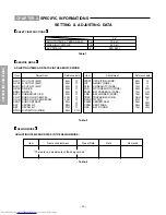
Page 18: ... BRTC COLP COLS SCNT SRY SBY HPOS R CUTOFF B W G CUTOFF B W B CUTOFF B W R DRIVE B DRIVE SUB BRIGHT CEN SUB COLOR CEN PAL SUB COLOR CEN SECAM SUB CONTRAST SECAM R Y SECAM B Y H POSITION WIDE Item Adjustment Reference data 40H 40H 40H 40H 40H 40H 3CH 3CH 07H 08H 07H 09H Item Adjustment Reference data VPOS1 HIT VLIN WID PARA CNR TRAP RAGC CSAW CPAR HSC V POSITION WIDE HEIGHT WIDE V LINEARITY WIDE PI...

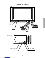
Page 19: ...EO L MONO AUDIO R 3 LOCATION OF CONTROLS MENU VOLUME DOWN VOLUME UP POSITION DOWN POSITION UP VIDEO 3 HEAD PHONE ON TIMER INDICATOR POWER INDICATOR MAIN SWITCH EXIT AERIAL TERMINAL VIDEO 1 21PINS FULL VIDEO 2 21PINS S VIDEO AV AUDIO OUT FIXED Front Rear terminals ...

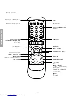
Page 20: ... SELECT SINGLE DIGIT DOUBLE DIGIT FLOF KEYS PICTURE MENU POSITION UP DOWN SELECT MENU OPTION SELECT MENU NOT USED FOR THIS MODEL 16 9 DISPLAY MUTE ON STAND BY POSITION NUMBER KEYS TEN KEYS VIDEO INPUT TEXT MODE SELECT OPTION VOLUME ADJUST LEVEL EXIT MENU STEREO BILINGUAL TEXT MODE HOLD REVEAL CONCEAL F T B FULL TOP BOTTOM TEXT CLEAR TIME DISPLAY TV MODE VCR CONTROL REWIND PLAY FAST WIND STOP ...

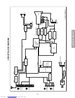
Page 21: ... L R TV L R AV SW 21PIN FULL 21PIN 3 FRONT 3 REAR MEMORY µ CON I 2 C BUS HYBRID CONVERTER TRANS B VOLTAGE RGB Y C Y C CHROMA VIDEO DEF Q501 Q302 VIDEO OUT VM V OUT H OUT EW F B T H V D Y V H CRT Q301 Q711 Q712 Q404 DPC Q901 Q903 Q905 1 2 I 2 C BUS CONTROL V L R S V L R HEAD PHONE Q608 AUDIO OUT L R QR01 SUB µ CON ...

Page 22: ...23 24503049 MT PLA CAP 63V 0 47UF J C325 24590223 PLASTIC FILM 50V 0 022MF J C326 24797010 ELECTROLYTIC CE04G 50V 1 0UF M C327 24794471 ELECTROLYTIC CE04G 16V 470UF M C329 24503045 MT PLA CAP 63V 0 22UF J C331 24503038 MT PLA CAP 63V 0 056UF J C332 24212102 CERAMIC DISK CK45 B 50V 1000PF K C341 24503049 MT PLA CAP 63V 0 47UF J C366 24082049 PLASTIC FILM CF922 M 100V 47000PF J C370 24794100 ELECTRO...

Page 23: ... CE04Q 25V 47UF M 3A C638 24667470 ELECTROLYTIC CE04Q 25V 47UF M 3A C639 24796102 ELECTROLYTIC CE04G 35V 1000UF M C641 24795470 ELECTROLYTIC CE04G 25V 47UF M C642 24797100 ELECTROLYTIC CE04G 50V 10UF M C643 24797479 ELECTROLYTIC CE04G 50V 4 7UF M C644 24668102 ELECTROLYTIC CE04Q 35V 1000UF M 3A C645 24668102 ELECTROLYTIC CE04Q 35V 1000UF M 3A C648 24797479 ELECTROLYTIC CE04G 50V 4 7UF M C649 24797...

Page 24: ...0UF M CR06 24797010 ELECTROLYTIC CE04G 50V 1 0UF M CR07 24797010 ELECTROLYTIC CE04G 50V 1 0UF M CR08 24353270 CERAMIC DISC CC45CH 50V 27PF J CV02 24797010 ELECTROLYTIC CE04G 50V 1 0UF M CV03 24797010 ELECTROLYTIC CE04G 50V 1 0UF M CV04 24794100 ELECTROLYTIC CE04G 16V 10UF M CV05 24797010 ELECTROLYTIC CE04G 50V 1 0UF M CV06 24797010 ELECTROLYTIC CE04G 50V 1 0UF M CV07 24794100 ELECTROLYTIC CE04G 16...

Page 25: ...ON FILM 1 6W 47K OHM J R433 24366103 CARBON FILM 1 6W 10K OHM J R433 24366681 CARBON FILM 1 6W 680 OHM J R434 24366271 CARBON FILM 1 6W 270 OHM J R434 24366472 CARBON FILM 1 6W 4 7K OHM J R435 24366184 CARBON FILM 1 6W 18OK OHM J R436 24366153 CARBON FILM 1 6W 15K OHM J R437 24366332 CARBON F1LM 1 6W 3 3K OHM J R438 24366103 CARBON FILM 1 6W 10K OHM J R439 24366102 CARBON FILM 1 6W 1K OHM J R441 2...

Page 26: ... 2W 220 OHM J R744 24366122 CARBON FILM 1 6W 1 2K OHM J R745 24366122 CARBON FILM 1 6W 1 2K OHM J R801 24009954 METAL FILN 1 2W 2 2M OHM J R803 24553683 OXIDE 1W 68K R805 24366681 CARBON FILM 1 6W 680 OHM J R808 24019484 THERMISTOR PTC THERMISTOR AC265 4R5A R814 24366682 CARBON FILM 1 6W 6 8K OHM J R815 24366332 CARBON F1LM 1 6W 3 3K OHM J R818 24019461 METAL PLATE 2W 0 15 OHM J R819 24310829 META...

Page 27: ...103 CARBON FILM 1 6W 10K OHM J RB09 24366470 CARBON FILM 1 6W 47 OHM J RB30 24366105 CARBON FILM 1 6W 1M OHM J RB30 24366103 CARBON FILM 1 6W 10K OHM J RB31 24366102 CARBON FILM 1 6W 1K OHM J RB32 24366332 CARBON F1LM 1 6W 3 3K OHM J RB33 24366332 CARBON F1LM 1 6W 3 3K OHM J RB35 24366102 CARBON FILM 1 6W 1K OHM J RB36 24366102 CARBON FILM 1 6W 1K OHM J RB37 24366221 CARBON FILM 1 6W 220 OHM J RB3...

Page 28: ...840 COIL PEAKING TRF4100AT L896 23103859 COIL CHOKE TEM2011 L901 23200404 COIL DG0 50CU60T 2LOOP 32 TSB 2395AM L908 23289840 COIL PEAKING TRF4100AT L911 23289846 COIL PEAKING TRF4101AT LA02 23103859 COIL CHOKE TEM2011 LA03 23289834 COIL PEAKING 1 00MMHK COLTRF41R0AT LA04 23103859 COIL CHOKE TEM2011 LA39 23103859 COIL CHOKE TEM2011 LB30 23289840 COIL PEAKING TRF4100AT LB31 23103859 COIL CHOKE TEM20...

Page 29: ...REW 3X8MM Q841 23314794 TRANSISTOR VCEO 50V TO 92 2PC1815Y Q842 23314794 TRANSISTOR VCEO 50V TO 92 2PC1815Y Q861 23314141 TRANSISTOR 2SC3852 Q861B 70391355 SCREW 3X8MM Q901 A6363200 TRANSISTOR 2SC3619 Q902 23314794 TRANSISTOR VCEO 50V TO 92 2PC1815Y Q903 A6363200 TRANSISTOR 2SC3619 Q904 23314794 TRANSISTOR VCEO 50V TO 92 2PC1815Y Q905 A6363200 TRANSISTOR 2SC3619 Q906 23314794 TRANSISTOR VCEO 50V T...

Page 30: ...148 DV06 23115599 DIODE 1N4148 MISCELLANEOUS B221 23037312 SCREW BB10B 23903022 CONNECTOR BASE B B 8P 2 5 JST BB11B 23903022 CONNECTOR BASE B B 8P 2 5 JST BB12B 23903022 CONNECTOR BASE B B 8P 2 5 JST BB13B 23903022 CONNECTOR BASE B B 8P 2 5 JST BB20B 23903022 CONNECTOR BASE B B 8P 2 5 JST F470 23144873 FUSE 1A 250V F470A 23165433 FUSE HOLDER 5 2 SOC F801 23144508 FUSE CARTRIDGE 5 2X20 250V 4 0A F8...

Page 31: ...016D 32Z13G U904A 23786016 PW UNIT CONT 1 PWU PD0017A 1 U904B 23786017 PW UNIT CONT 2 PWU PD0017A 2 PICTURE TUBE V901 23312885 PICTURE TUBE 32W 50HZ FLAT W76EJS011X107 TUNER H001 23321413 TUNER ALPS UK TEDB7 205A 32Z13B H001 23321370 TUNER TN EGA51L 32Z13G ACCESSORIES K902 23306363 REMOCON HAND UNIT IR CTVPAL CT 90040 Y101 23565270 OWNER S MANUAL ENGLISH 28Z13B 32 28Z13B ENG Y101 23565287 OWNER S ...

Page 32: ... 32 SPECIFIC INFORMATIONS THIS PAGE IS INTENTIONALLY LEFT BLANK ...

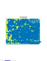
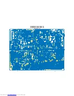
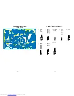
Page 33: ... 33 34 SIGNAL BOARD PD0015C SIGNAL BOARD PD0015D BOTTOM FOIL SIDE ...

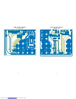
Page 34: ... 35 36 POWER DEF BOARD PD0016C POWER DEF BOARD PD0016D BOTTOM FOIL SIDE ...

Page 35: ... 37 38 CONT 1 BOARD PD0017A 1 BOTTOM FOIL SIDE CONT 2 BOARD PD0017A 2 BOTTOM FOIL SIDE ...

Page 36: ... 2SD1763A 2SC1569 2SC4544 2SA1788 2SA1306 2SA1186A 2SC752GTM 2SC2482 2SC2655 2SC4721P 2SC752 2SA562TM 2SA1015 2SC1815 2SC2878 2SC1740S 2SC2120 2SA9335 2SA1788 RN2203 RN2201 RN2004 RN1203 RN1204 RN2204 RN1205 RN1202 RN1201 2SD1554 2SD2253 2SD1556 2SC5143 2SD2553 E C B B C E B CE B C E E C B ON4409 B CE E C B B C E ...

Page 37: ... 41 SPECIFIC INFORMATIONS MEMO ...

Page 38: ... 42 SPECIFIC INFORMATIONS MEMO ...

Page 39: ...TSC For VCR playback 3 58 NTSC For VCR playback Intermediate Frequencies Picture I F carrier frequency 38 9 MHz L VL Sound I F carrier frequency 32 9 MHz Picture Tube 32 inches 760 mm measured on diagonal of viewable picture area 106 deflection Sound Output 5 W 5 W at 10 Distortion Main Speakers 60 mm x 120 mm oval 2 pcs Main Aux Terminals 21 pin socket FULL 21 pin socket S VIDEO AV MONITOR OUTPUT...

Page 40: ......
Reviews: