– 10 –
GENERAL ADJUSTMENTS
SPECIFIC INFORMATIONS
ELECTRICAL ADJUSTMENTS
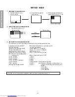
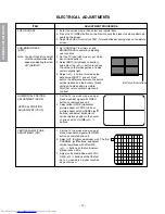
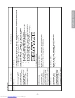
1. Enter the service mode, then select any register item.
2. Press the TV/VIDEO button on the Remote until the black cross-bar pattern ap-
pears on the screen.
3. Adjust the FOCUS control (on T461) for well defined scanning lines on the picture
screen.
FOCUS VR ADJ
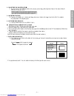
SUB-BRIGHTNESS
(BRTC)
Note: Constrict the picture height
until the vertical retrace line
appears adjusting the item
HIT (HEIGHT).
1. Set CONTRAST to minimum, and
BRIGHTNESS to center by adjusting
user controls.
2. Set the TV in service mode to get cross-
bar of inside pattern.
3. Select BRTC (brightness correction),
and adjust the
;
– /+ button to reduce
the value so that white portion of inside
pattern slightly light.
4. Adjust
;
– /+ button to increase the
data value of BRTC, and set it just
before the difference between the belt of
vertical retrace and the border of black
portion of inside pattern is visible.
After that, return vertical height and
contrast.
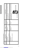
ITEM
ADJUSTMENT PROCEDURE
Belt of vertical retrace
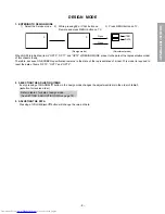
HORIZONTAL POSITION
ADJUSTMENT (HPOS)
VERTICAL POSITION
ADJUSTMENT (VPOS)
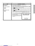
1. Set the TV in service mode, and get
black cross-bar signal with VIDEO
button on remote hand unit.
2. Select either HPOS (Horizontal
picture phase) or VPOS (Vertical
picture phase) with CHANNEL
s
,
t
buttons, and adjust horizontal or
vertical picture position in the center
of screen with VOLUME
;
– /+
buttons.
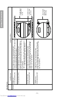
VERTICAL AMPLITUDE
ADJUSTMENT (HIT)
1. Set the TV in service mode, and get
black cross-hatch signal with VIDEO
button on remote hand unit.
2. Select HIT (Vertical amplitude) with
CHANNEL
s
,
t
buttons, and adjust
vertical amplitude with VOLUME
;
– /+ buttons so that vertical am-
plitude lacks a little.
3. Adjust vertical amplitude with VOL-
UME
;
– /+ buttons so that the first
bar on cross-hatch signal touches
edge of screen.
The first
Summary of Contents for 32Z13B
Page 32: ... 32 SPECIFIC INFORMATIONS THIS PAGE IS INTENTIONALLY LEFT BLANK ...
Page 33: ... 33 34 SIGNAL BOARD PD0015C SIGNAL BOARD PD0015D BOTTOM FOIL SIDE ...
Page 34: ... 35 36 POWER DEF BOARD PD0016C POWER DEF BOARD PD0016D BOTTOM FOIL SIDE ...
Page 35: ... 37 38 CONT 1 BOARD PD0017A 1 BOTTOM FOIL SIDE CONT 2 BOARD PD0017A 2 BOTTOM FOIL SIDE ...
Page 37: ... 41 SPECIFIC INFORMATIONS MEMO ...
Page 38: ... 42 SPECIFIC INFORMATIONS MEMO ...
Page 40: ......


