– 14 –
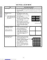
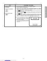
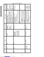
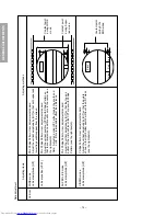
GENERAL ADJUSTMENTS
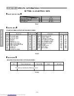
SPECIFIC INFORMATIONS
V
e
rtical
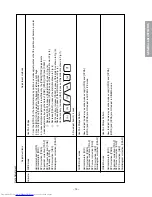
WIDE mode
V
e
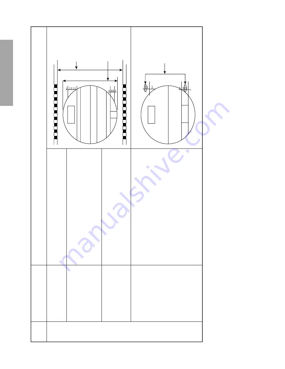
rtical amplitude [HIT]
V
e
rtical position [VPS1]
SUPER LIVE mode
V
e
rtical amplitude [HIT]
CINEMA mode
V
e
rtical amplitude [HIT]
P
AL Philips P
atter
n, User adjustment standard
Adjust the v
e
rtical amplitude b
y [HIT] so that both upper and
lo
w
er flags will disappear from the screen.
P
AL Philips P
atter
n, User adjustment standard
Adjust the v
e
rtical position [VPS1] with Philips P
atter
n so
that the v
e
rtical screen position will come to the center (see
the r
ight sk
etch)
Note:
Adjust and or
ient CPT either to
w
ard the south and
nor
th.
If this is impossib
le
, offset the diff
erence
.
P
AL Philips P
atter
n, User adjustment standard
Adjust the v
e
rtical amplitude b
y
[HIT] so that the top and
bottom of the circle will touch the CPT mask with Philips
P
atter
n (see the r
ight sk
etch).
Phillips P
atter
n, User adjustment standard
Adjust the v
e
rtical amplitude b
y
[HIT] so that the points
sho
wn in the r
ight bottom sk
etch will touch the CR
T mask
(see the r
ight sk
etch).
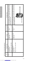
Adjusting items
Adjusting methods
Contact point
dur
ing WIDE
mode
Contact point
dur
ing Super-
liv
e mode
Blac
k
Y
ello
w
Red
Y
ello
w
Contact point
dur
ing CIN-
EMA mode
Data adjustment
Summary of Contents for 32Z13B
Page 32: ... 32 SPECIFIC INFORMATIONS THIS PAGE IS INTENTIONALLY LEFT BLANK ...
Page 33: ... 33 34 SIGNAL BOARD PD0015C SIGNAL BOARD PD0015D BOTTOM FOIL SIDE ...
Page 34: ... 35 36 POWER DEF BOARD PD0016C POWER DEF BOARD PD0016D BOTTOM FOIL SIDE ...
Page 35: ... 37 38 CONT 1 BOARD PD0017A 1 BOTTOM FOIL SIDE CONT 2 BOARD PD0017A 2 BOTTOM FOIL SIDE ...
Page 37: ... 41 SPECIFIC INFORMATIONS MEMO ...
Page 38: ... 42 SPECIFIC INFORMATIONS MEMO ...
Page 40: ......


