– 12 –
GENERAL ADJUSTMENTS
SPECIFIC INFORMATIONS
(Reference Factory Adjustments)
Items
Names
Settings
Input signals
Measur
ing points
Adjusting methods
Adjusting standards
N/A
N/A
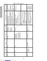
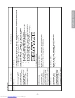
Picture MODE-1
NO need
0% modulation
100dBuV Le
v
e
l
F
actor
y Gen 206A
Set polar
ity re
v
erse
Set system to
WG
Sub-br
ight signal
Usual case
OSD Chec
k
Rare case
TP16 or
Q501 #55 pin
OSD Chec
k
Screen adjust-
ment
Put set into Ser
vice mode
Chec
k OSD if it is
“COIL OK
”.
If OSD is
“COIL NG
” contin
ue ne
xt action.
Send AFT adj code b
y HHU command.
With data displa
y
ed on screen press
“0
” on
HHU (This is code 40 BF F6)
Connect a v
olt-meter to pin 55 of the Q501.
Then adjust the L161.
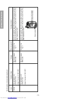
A)
Open IF and A
GC solder pads
Apply input signal
Put set into S mode
Send A
GC code 40 BF F7
W
ait f
or OSD displa
y to change to
“AG
C
OK
”
B)
or
F
eed-in the colour Bar Signal with sound
(RF 90dBuV)
Adjust A
GC Bus data so as to get the good
S/N picture and no inter modulation ap-
pearance
1
.
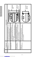
This item shall be adjusted after the
screen
VR adjustment and white balance
adjustment
2
.
Adjust the n
umber of collapsed b
lac
k lines
of the sub-br
ight signal
In case of
“COIL
OK
”
N/A
IC A
uto Adjust
In case of
“COIL
NG
”
V
oltage of pin 55
2.5
±
1V
N/A
IC A
uto Adjust
32
”:
32Z13B/
32Z13G
4
±
1.5 lines
28
”:
28Z13B/
28Z13G
4
±
1.5 lines
VCO
AG
C
BR
TC
VCO
AG
C
Sub-br
ight
adjustment
Summary of Contents for 32Z13B
Page 32: ... 32 SPECIFIC INFORMATIONS THIS PAGE IS INTENTIONALLY LEFT BLANK ...
Page 33: ... 33 34 SIGNAL BOARD PD0015C SIGNAL BOARD PD0015D BOTTOM FOIL SIDE ...
Page 34: ... 35 36 POWER DEF BOARD PD0016C POWER DEF BOARD PD0016D BOTTOM FOIL SIDE ...
Page 35: ... 37 38 CONT 1 BOARD PD0017A 1 BOTTOM FOIL SIDE CONT 2 BOARD PD0017A 2 BOTTOM FOIL SIDE ...
Page 37: ... 41 SPECIFIC INFORMATIONS MEMO ...
Page 38: ... 42 SPECIFIC INFORMATIONS MEMO ...
Page 40: ......


