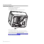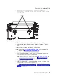
d. Lift the paper door assembly off its posts at the rear of the unit.
To replace the cutter motor and paper door assembly, complete the following steps:
1. Position the door assembly over the posts; then align the hinges on the door
assembly with the posts on the unit.
2. Set the door assembly on to the posts and hold it in the fully open position.
3. Align the drag strip with the retention bracket on the side of the unit.
4. Close the door assembly slightly while inserting the drag strip into the retention
bracket. You will hear the drag strip click as it passes the detent.
Note:
Do not close the door completely.
5. Install the lift spring:
a. Orient the printer unit with one side facing you.
b. Orient the spring with the short leg facing up and toward the printer unit
frame.
c. Place the spring onto the post and rotate the short leg of the spring enough
to avoid contact with the paper door assembly.
d. Align the end of the spring leg with the slot and hole in the paper door
assembly; then rotate the bottom of the spring toward the front of the printer
unit and insert the hooked end into the mounting slot.
e. Repeat steps 5a through 5d to install the remaining spring; then, continue to
the next step.
6. Install the cutter motor:
a. Align the mounting holes in the motor with the holes in mounting bracket.
b. Install the mounting screws and secure the cutter motor.
7. Route the wires from the cutter motor and paper door assembly around the right
side of the printer unit frame.
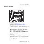
8. Connect the cable to the logic card; then install the logic card (see “Removing
the logic card” on page 60 for information on how to install the logic card).
9. Install the main and top covers (see “Removing the main cover” on page 55 and
“Removing the top cover” on page 53).
Removing the rollers
To remove the rollers, complete the following steps:
Note:
Only use this procedure if you are replacing all rollers and the lift springs. If
you are only replacing the rollers (excluding the top roller), you only need to
open the top cover and proceed to Step 3 on page 65.
1. Remove the paper door assembly and lift springs (see “Removing the cutter
motor and paper door assembly” on page 62 to remove the lift springs and
paper door assembly).
Note:
You do not need to remove the cutter motor or disconnect its cable from
the logic card.
2. Remove the topmost roller by pushing apart the paper door assembly posts and
pulling it out of its holes.
Removing and replacing FRUs
64
SureMark Hardware Service
Summary of Contents for 1NA
Page 2: ......
Page 8: ...vi SureMark Hardware Service ...
Page 10: ...viii SureMark Hardware Service ...
Page 12: ...x SureMark Hardware Service ...
Page 16: ...xiv SureMark Hardware Service ...
Page 18: ...xvi SureMark Hardware Service ...
Page 46: ...28 SureMark Hardware Service ...
Page 56: ...38 SureMark Hardware Service ...
Page 88: ...70 SureMark Hardware Service ...
Page 90: ...Assembly 1 Models 1NR 1NA and 1ND 1 2 3 4 5 7 6 72 SureMark Hardware Service ...
Page 92: ...Assembly 1 continued 74 SureMark Hardware Service ...
Page 108: ...90 SureMark Hardware Service ...
Page 109: ......
Page 110: ...G362 0565 05 ...

