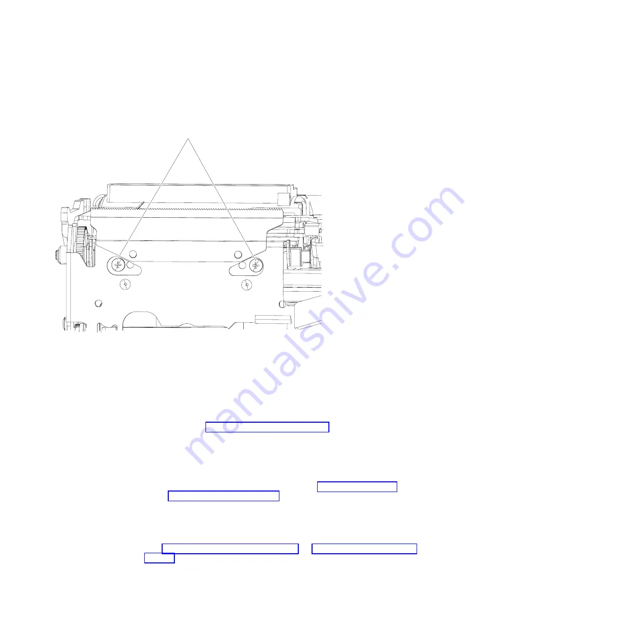
4. While supporting the printhead with one hand, use a screwdriver with a
magnetic head to remove the mounting screws; then lift the printhead partially
out of the printer.
5. Disconnect the thermal printhead flat cable from the bottom of the printhead.
6. Disconnect the ribbon cable that connects the thermal printhead to the logic
card.
To replace thermal printhead, complete the following steps:
Note:
When you replace the thermal printhead, run the offline test to reset the
statistics. See “Firmware offline tests” on page 45.
1. Orient the printer so the front of the unit is facing you.
2. Hold the printhead with the two black bars or print surface facing away from
you; then connect the flat cable to the printhead
Note:
Ensure the contacts on the flat cable are facing toward you. If they are
not, then remove and install the cable (see “Removing the thermal
printhead flat cable” on page 61 for information).
3. Place the unit on its back.
4. Align the threaded holes in the printhead with the mounting holes in the frame;
then use screws to secure the printhead in place.
5. Install the main cover, top covers, and reconnect the signal and power cables
(see “Removing the main cover” on page 55 and“Removing the main cover” on
page 55 for information).
Screws
Figure 20. Paper door release lever
Removing and replacing FRUs
Chapter 5. Removing and replacing FRUs
59
Summary of Contents for 1NA
Page 2: ......
Page 8: ...vi SureMark Hardware Service ...
Page 10: ...viii SureMark Hardware Service ...
Page 12: ...x SureMark Hardware Service ...
Page 16: ...xiv SureMark Hardware Service ...
Page 18: ...xvi SureMark Hardware Service ...
Page 46: ...28 SureMark Hardware Service ...
Page 56: ...38 SureMark Hardware Service ...
Page 88: ...70 SureMark Hardware Service ...
Page 90: ...Assembly 1 Models 1NR 1NA and 1ND 1 2 3 4 5 7 6 72 SureMark Hardware Service ...
Page 92: ...Assembly 1 continued 74 SureMark Hardware Service ...
Page 108: ...90 SureMark Hardware Service ...
Page 109: ......
Page 110: ...G362 0565 05 ...


