


G009680
1
2
3
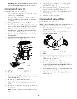
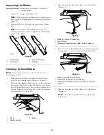
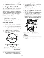
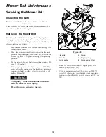
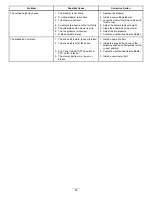
Figure 45
1.
Opposite blade edge (in position for measuring)
2.
Level surface
3.
Second measured distance between blade and surface (B)
A.
If the difference between A and B is greater than
3mm (1/8 inch), replace the blade with a new
blade; refer to Removing the Blades (page 34) and
Installing the Blades (page 34).
Note:
If a bent blade is replaced with a new one,
and the dimension obtained continues to exceed
3mm (1/8 inch), the blade spindle could be bent.
Contact an Authorized Toro Dealer for service.
B.
If the variance is within constraints, move to the
next blade.
Repeat this procedure on each blade.
Removing the Blades
The blades must be replaced if a solid object is hit, if the
blade is out of balance, or if the blade is bent. To ensure
optimum performance and continued safety conformance
of the machine, use genuine Toro replacement blades.
Replacement blades made by other manufacturers may result
in non-conformance with safety standards.
1.
Hold the blade end using a rag or thickly-padded glove.
2.
Remove the blade bolt, the curved washer, the blade
stiffener, and the blade from the spindle shaft (Figure
46).
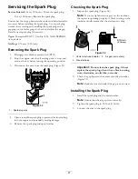
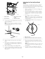
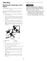
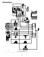
Figure 46
1.
Sail area of the blade
4.
Blade bolt
2.
Blade
5.
Blade stiffener
3.
Curved washer
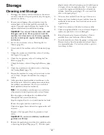
Sharpening the Blades
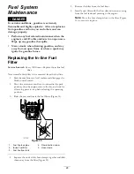
1.
Use a file to sharpen the cutting edge at both ends of
the blade (Figure 47).
Note:
Maintain the original angle.
Note:
The blade retains its balance if the same amount
of material is removed from both cutting edges.
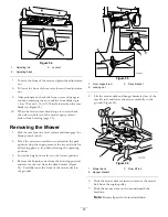
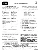
Figure 47
1.
Sharpen at original angle
2.
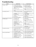
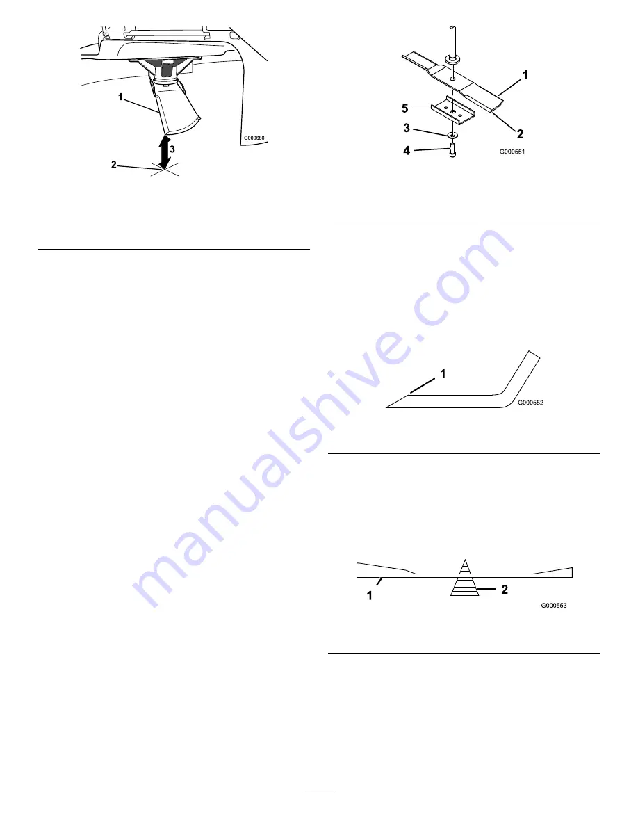
Check the balance of the blade by putting it on a blade
balancer (Figure 48).
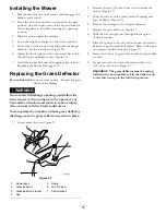
Note:
If the blade stays in a horizontal position, the
blade is balanced, and can be used.
Note:
If the blade is not balanced, file some metal off
the end of the sail area only (Figure 47).
Figure 48
1.
Blade
2.
Balancer
3.
Repeat this procedure until the blade is balanced.
Installing the Blades
1.
Install the blade onto the spindle shaft (Figure 46).
Important:
The curved part of the blade must be
pointing upward toward the inside of the mower to
ensure proper cutting.
34
Summary of Contents for TimeCutter SS 3216
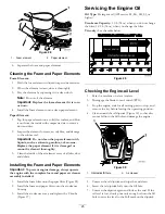
Page 44: ...Schematics G014644 Electrical Diagram Rev A 44 ...
Page 45: ...Notes 45 ...
Page 46: ...Notes 46 ...
Page 47: ...Notes 47 ...


