

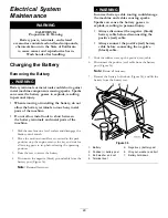


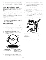
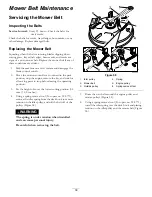


Inspecting the Blades
Service Interval:
Before each use or daily—Check the
cutting blades.
1.
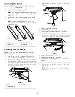
Inspect the cutting edges (Figure 41).
Note:
If the edges are not sharp or have nicks, remove
and sharpen the blades; refer to Sharpening the Blades
(page 34).
2.
Inspect the blades, especially the curved area (Figure
41).
Note:
If you notice any damage, wear, or a slot
forming in this area (item 3 in Figure 41), immediately
install a new blade.
Figure 41
1.
Cutting edge
3.
Wear/slot forming
2.
Curved area
4.
Damage
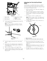
Checking for Bent Blades
Note:
The machine must be on a level surface for the
following procedure.
1.
Raise the mower deck to the highest height-of-cut
position; also considered the 'transport' position.
2.
While wearing thickly padded gloves, or other adequate
hand protection, slowly rotate the blade to be measure
into a position that allows effective measurement of the
distance between the cutting edge and the level surface
the machine is on (Figure 42).
G009679
1
2
3
Figure 42
1.
Deck
3.
Blade
2.
Spindle housing
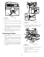
3.
Measure from the tip of the blade to the flat surface
(Figure 43).
G009680
1
2
3
Figure 43
1.
Blade (in position for measuring)
2.
Level surface
3.
Measured distance between blade and the surface (A)
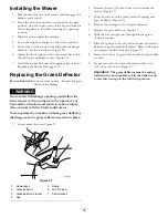
4.
Rotate the same blade 180 degrees, so that the opposing
cutting edge is now in the same position (Figure 44).
G009681
1
2
3
Figure 44
1.
Blade (side previously measured)
2.
Measurement (position used previously)
3.
Opposing side of blade being moved into measurement
position
5.
Measure from the tip of the blade to the flat surface
(Figure 45).
Note:
The variance should be no more than 3mm
(1/8 inch).
33
Summary of Contents for TimeCutter SS 3216
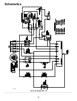
Page 44: ...Schematics G014644 Electrical Diagram Rev A 44 ...
Page 45: ...Notes 45 ...
Page 46: ...Notes 46 ...
Page 47: ...Notes 47 ...