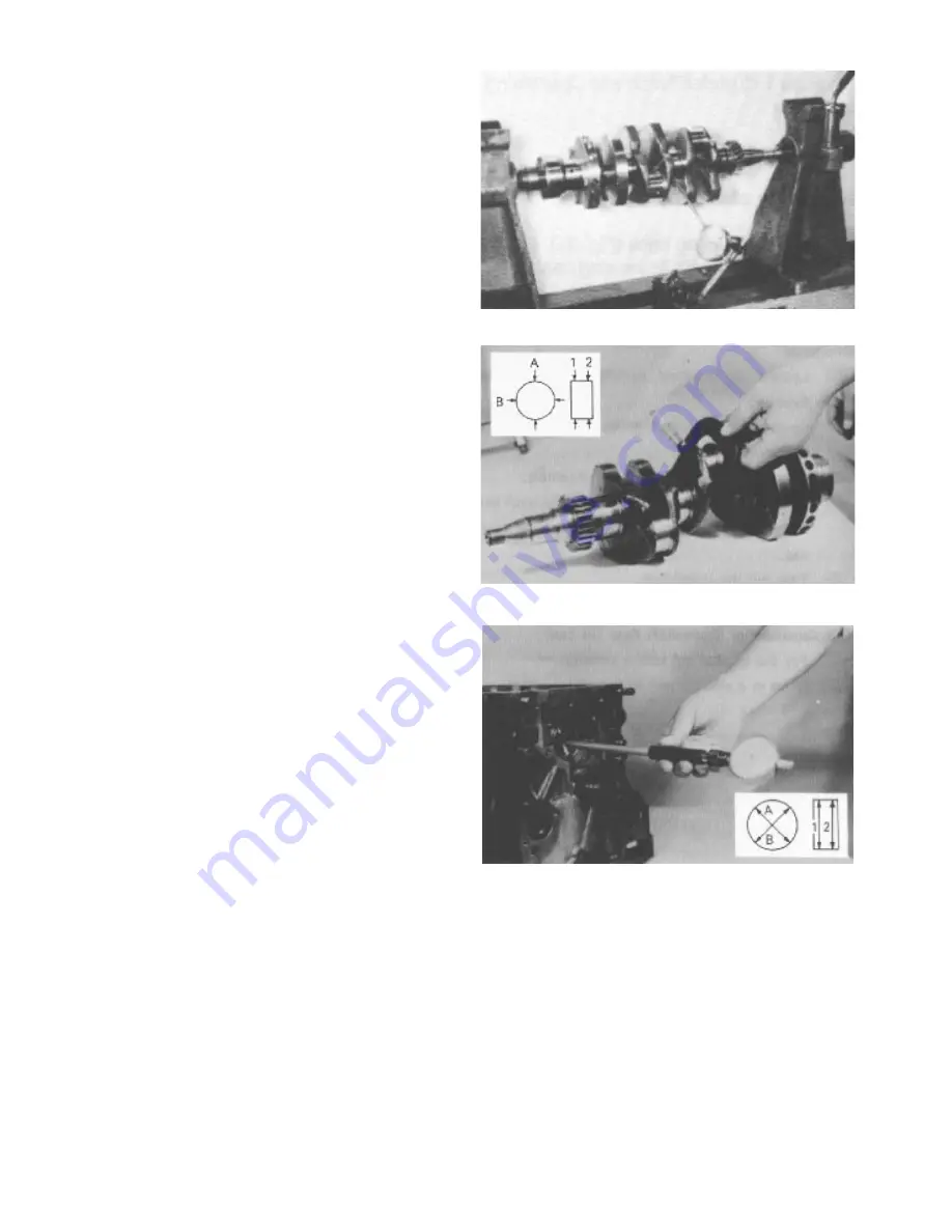
6. Measure the crankshaft for “run-out” (bend). Mount
the crankshaft in a pair of V-blocks (or live centers) and
use a dial indicator to measure the run-out in the crank
shaft (Fig. 103). The maximum allowable crankshaft
run-out is 0.05 mm (0.002 in.).
7. Check the crank journals and crankpins for damage,
out of round wear or tapering wear. The diameter of each
crankpin or main journal should be measured at two
places, “1" and ”2", in two directions, “A” and “B”
(Fig. 104).
Main journal diameter: 42.3 mm (1.665 in.) minimum
Crankpin diameter: 39.3 mm (1.547 in.) minimum
8. Check the crankshaft oil clearance. Oil clearance is
calculated by subtracting the diameter of the main jour
nal or crankpin from the inside diameter of the main
bearing or rod bearing. The inside diameter of each
crankpin or main journal should be measured at two
places, “1" and ”2", in two directions, “A” and “B”
(Fig. 105) after the bearing cap is installed at the proper
torque. If the oil clearance exceeds the service limits,
install a new bearing. If installing the new bearing does
not reduce the clearance to within service limits, the
crankshaft must be reground and oversize bearings
installed.
Tightening Torque:
Main bearing cap bolt 5.0 - 5.5 KgM (23 - 25 ft-lb)
Rod bearing cap nut 3.2 - 3.5 KgM (36 - 40 ft-lb)
Crankpin oil clearance: 0.15 mm (0.006 in.)
Journal oil clearance: 0.10 mm (0.004 in.)
NOTE: If using Plastigauge to measure the oil clear
ance, put a piece of Plastigauge onto the crankpin or
journal, and tighten the bearing cap (with bearing) in
place. DO NOT rotate connecting rod or crankshaft
when the Plastigauge is in place. Rotating will destroy
the Plastigauge. Remove the bearing cap and measure
the width of the Plastigauge to determine the clearance.
If the oil clearance exceeds the service limits, install a
new bearing. If installing the new bearing does not
reduce the clearance to within service limits, the crank
shaft must be reground and oversize bearings installed.
9. To install a new oil seal, pry the seal out with a
screwdriver and drive a new seal into the oil seal case.
Figure 93
Figure 94
Figure 95
Cylinder Block Overhaul
Page 3 - 64
Reelmaster
®
223-D/5100-D
Summary of Contents for Reelmaster 5100-D
Page 2: ...This page is blank ...
Page 4: ...This page is blank ...
Page 8: ...Safety Instructions Page 1 4 Reelmaster 5100 D ...
Page 12: ...Maintenance Interval Chart Maintenance Interval Chart Page 2 4 Rev A Reelmaster 5100 D ...
Page 32: ...Troubleshooting Page 3 16 Reelmaster 223 D 5100 D ...
Page 33: ...Reelmaster 223 D 5100 D Page 3 17 Troubleshooting ...
Page 86: ...Specifications Page 4 2 2 Reelmaster 5100 D ...
Page 90: ...Hydraulic Schematic Rev A Hydraulic Schematic Page 4 6 Reelmaster 5100 D ...
Page 154: ...Logic Chart Page 5 2 Reelmaster 5100 D ...
Page 155: ...Wiring Schematic S N Below 51001 Rev B Reelmaster 5100 D Page 5 3 Wiring Schematic ...
Page 206: ...Repairs Page 5 48 Rev A Reelmaster 5100 D ...
Page 230: ...Repairs Page 6 24 Reelmaster 5100 D ...
Page 304: ...Repairs Page 8 22 Reelmaster 223 D 5100 D 5300 D ...
Page 317: ...This page is blank ...


