background image

Special Tools

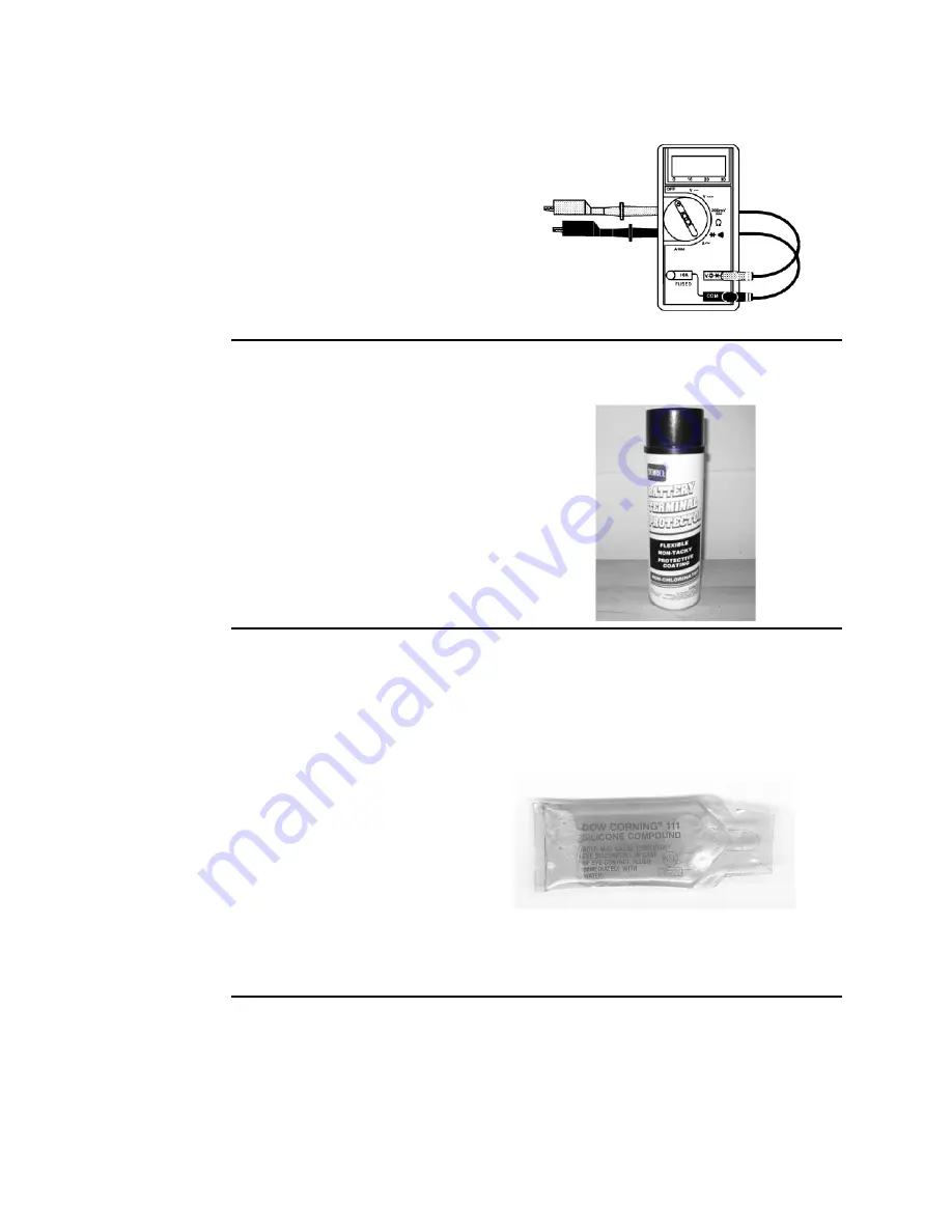
Multimeter

Obtain this tool locally

The meter can test the electrical
components and circuits for current,
resistance, or voltage.

Note:

Use a digital multimeter when

testing the electrical circuits. The high
impedance (internal resistance) of a digital
meter in the voltage mode ensures that
the excess current is not allowed through
the meter. This excess current can
damage the circuits that are not designed
to carry it.

Battery Terminal Protector

Toro Part No. 107-0392

Use this aerosol spray on the battery
terminals, ring terminals, and fork terminals
to reduce corrosion problems. Apply the
terminal protector to the connection after
you secure the battery cable, ring terminal,
or fork terminal.

Dielectric Gel

Toro Part No. 107-0342

Use the dielectric gel to prevent
corrosion of unsealed connection
terminals. To ensure complete
coating of the terminals, liberally
apply the gel to the component
and wire harness connector, plug
the connector into the component,
disconnect the connector, apply
the gel to both surfaces again, and
connect the harness connector
to the component again. The
connectors must be fully packed
with gel for effective results.

Note:

Do not use the dielectric gel

on the sealed connection terminals
as the gel can unseat the connector
seals during assembly.

Specifications and Maintenance: Special Tools

Page 2–12

Pro Force® Debris Blower

18237SL Rev A

Summary of Contents for Pro Force 44552

Page 1: ...8237SL Rev A Pro Force Debris Blower Models 44552 44552TE 44553 44554 2019 The Toro Company 8111 Lyndale Avenue South Bloomington MN 55420 Original Instructions EN Contact us at www Toro com All Rights Reserved ...

Page 2: ...Revision History Revision Date Description A 01 2019 Initial Issue Revision History Page 2 Pro Force Debris Blower 18237SL Rev A ...

Page 3: ...ctively we encourage user feedback Please comment on the completeness accuracy organization usability and readability of this manual by e mail servicemanuals toro com by mail Technical Publication Manager Commercial The Toro Company 8111 Lyndale Avenue South Bloomington MN 55420 1196 Phone 1 952 887 8495 Pro Force Debris Blower Page 3 Reader Comments 18237SL Rev A ...

Page 4: ...Reader Comments Page 4 Pro Force Debris Blower 18237SL Rev A ...

Page 5: ...ucts Refer to the Table of Contents for a list of the systems and the related topics covered in this manual Refer to the machine Operator s Manual for additional information about operating maintaining and adjusting the machine Keep a copy of the Operator s Manuals Installation Instructions and Parts Catalog for your machine and its accessories with this Service Manual for reference Additional cop...

Page 6: ...ue This icon is used to highlight an assembly torque requirement that is different than what is recommended in the Standard Torque Tables refer to Standard Torque for Dry Zinc Plated and Steel Fasteners Inch Series page 2 7 or Standard Torque for Dry Zinc Plated and Steel Fasteners Metric Fasteners page 2 8 Fluid Specifications This icon is used to highlight fluid specifications and capacities tha...

Page 7: ...5 1 General Information 5 2 Electrical System Quick Checks 5 6 Testing the Electrical Components 5 8 Service and Repairs 5 31 Chapter 6 Blower Assembly 6 1 General Information 6 2 Service and Repairs 6 3 Chapter 7 Chassis 7 1 General Information 7 2 Service and Repairs 7 3 Appendix A A 1 Electrical Drawing Designations A 2 Electrical Schematic Models 44552 44552TE and 44553 A 3 Electrical Schemati...

Page 8: ...Preface Page 8 Pro Force Debris Blower 18237SL Rev A ...

Page 9: ...Chapter 1 Safety Table of Contents Safety Instructions 1 2 Think Safety First 1 3 Jacking Instructions 1 6 Safety and Instructional Decals 1 6 Pro Force Debris Blower Page 1 1 Safety 18237SL Rev A ...

Page 10: ... can result in serious injury CAUTION This safety symbol means caution When you see this symbol carefully read the instructions that follow Failure to obey the instructions can result in minor to moderate injury IMPORTANT The Important notice will give the important instructions which you must follow to prevent damage to the systems or components on the machine Note A Note will give the general in...

Page 11: ...ential to start Avoid burns Do not touch the engine muffler or other components which may be hot during operation while the unit is running or shortly after it has been running Avoid fires and explosions Use extreme care in handling fuel Fuel is flammable and its vapors are explosive Extinguish all cigarettes cigars pipes and other sources of ignition Avoid spilling fuel and never smoke while work...

Page 12: ... fluid escaping under pressure can have sufficient force to penetrate the skin and cause serious injury Seek medical attention right away if hydraulic fluid gets in the skin Use personal protective equipment Use appropriate personal protective equipment PPE for protecting yourself from potential hazards in the environment in which you will work Each process outlined in this manual may need differe...

Page 13: ...bustible liquids such as gasoline kerosene grease and oil The numerical rating for class B extinguishers indicates the approximate number of square feet of fire it can extinguish Geometric symbol red square Class C fire extinguishers are for fires that involve electrical equipment such as appliances wiring circuit breakers and outlets Never use water to extinguish class C fires the risk of electri...

Page 14: ...ck the blower wheels with chocks to prevent the machine from moving or leave the blower attached to a tow vehicle if possible Engage the tow vehicle parking brake shut off the tow vehicle engine and remove the key from the tow vehicle key switch if applicable g233699 Figure 1 1 Wheel 2 Frame jacking point 2 Position the jack securely under the main frame of the blower Do not use the axle as a jack...

Page 15: ...en Using a Drive Adapter Wrench 2 5 Identifying the Fastener 2 6 Standard Torque for Dry Zinc Plated and Steel Fasteners Inch Series 2 7 Standard Torque for Dry Zinc Plated and Steel Fasteners Metric Fasteners 2 8 Other Torque Specifications 2 9 Conversion Factors 2 9 Shop Supplies 2 10 Special Tools 2 12 Pro Force Debris Blower Page 2 1 Specifications and Maintenance 18237SL Rev A ...

Page 16: ...Specifications Overall Dimensions g274940 Figure 2 Specifications and Maintenance Specifications Page 2 2 Pro Force Debris Blower 18237SL Rev A ...

Page 17: ...nk capacity 18 9 L 5 US gallons Air cleaner Dual element Lubrication system Pressure lubrication with oil cooler Crankcase oil capacity 2 0 L 67 fl oz Engine oil Refer to the Operator s Manual Ignition system Flywheel magneto twin electronic armatures with ignition advance Spark plug Champion RC12YC Champion Platinum 3071 or equivalent Spark plug gap 0 76 mm 0 030 inch Starter 12 VDC solenoid shif...

Page 18: ... hardness of the surface underneath the head of the fastener or similar condition which affects the installation As noted in the following tables the torque values should be reduced by 25 for lubricated fasteners or fasteners with a wet thread locking compound applied to achieve the similar stress as a dry fastener The torque values must be reduced when the fastener is threaded into the aluminum o...

Page 19: ...rque When using a torque wrench with a drive adapter wrench the calculated torque will be lower than the listed torque recommendation Example The measured effective length of the torque wrench distance from the center of the handle to the center of the square drive is 457 mm 18 inches The measured effective length of the torque wrench with the drive adapter wrench installed distance from the cente...

Page 20: ...ed into the fastener and pre applied dry thread locking compound Keep in mind a fastener with a locking feature usually means there will be friction during initial installation and during removal Toro recommends replacing fasteners with a locking feature once they have been removed because the effectiveness of the locking feature diminishes with each reuse If it is necessary to reuse a fastener wi...

Page 21: ...5 68 7 70 7 95 9 7 16 20 UNF 29 3 29 3 39 4 55 6 75 8 77 8 104 11 1 2 13 UNC 30 3 48 7 65 9 75 8 102 11 105 11 142 15 1 2 20 UNF 32 4 53 7 72 9 85 9 115 12 120 12 163 16 5 8 11 UNC 65 10 88 12 119 16 150 15 203 20 210 21 285 28 5 8 18 UNF 75 10 95 15 129 20 170 18 230 24 240 24 325 33 3 4 10 UNC 93 12 140 20 190 27 265 27 359 37 375 38 508 52 3 4 16 UNF 115 15 165 25 224 34 300 30 407 41 420 43 56...

Page 22: ...m M20 X 2 5 325 33 ft lb 440 45 N m 450 46 ft lb 610 62 N m Note Reduce the torque values listed in the table above by 25 for lubricated fasteners Lubricated fasteners are defined as threads coated with a lubricant such as engine oil or a thread sealant such as Loctite Note The torque values must be reduced when installing the fasteners into threaded aluminum or brass The specified torque value sh...

Page 23: ... lb 88 14 N m 1 2 20 UNF Grade 5 80 10 ft lb 108 14 N m M12 X 1 25 Class 8 8 80 10 ft lb 108 14 N m M12 X 1 5 Class 8 8 80 10 ft lb 108 14 N m For steel wheels and non lubricated fasteners Thread Cutting Screws Zinc Plated Steel Threads per Inch Thread Size Type A Type B Baseline Torque No 6 18 20 20 5 in lb No 8 15 18 30 5 in lb No 10 12 16 38 7 in lb No 12 11 14 85 15 in lb The hole size materia...

Page 24: ...ter fastener installation Most thread locking compounds allow the fastener to be removed with standard tools once cured High strength thread locking compounds may require applying heat to the fastener and the surrounding area to allow fastener removal Note Some fasteners have a dry thread locking compound pre applied Patch Loc so no additional thread locking compound is necessary when installing a...

Page 25: ...ical residue and previously used gaskets or gasket compounds SILICONE SEALANT Designed for a broad variety of sealing and bonding requirements silicone sealants are usually room temperature vulcanizing RTV which form a flexible silicone rubber that bonds to a wide variety of smooth or porous materials when cured Standard silicone sealants are designed to perform in temperatures from 51 F to 232 C ...

Page 26: ...ems Apply the terminal protector to the connection after you secure the battery cable ring terminal or fork terminal Dielectric Gel Toro Part No 107 0342 Use the dielectric gel to prevent corrosion of unsealed connection terminals To ensure complete coating of the terminals liberally apply the gel to the component and wire harness connector plug the connector into the component disconnect the conn...

Page 27: ...o ensure that proper torque is applied to the nut Shaft Alignment Tool Toro Part No 137 6616 The shaft alignment tool is used to align the engine output shaft with the blower shaft if the engine blower drive shaft or blower assembly is removed The tool also sets the proper distance between the engine and blower assembly Pro Force Debris Blower Page 2 13 Specifications and Maintenance Special Tools...

Page 28: ...Specifications and Maintenance Special Tools Page 2 14 Pro Force Debris Blower 18237SL Rev A ...

Page 29: ...nfirmation 3 2 Using the Onboard Diagnostic Lamp 3 3 Entering Diagnostic Mode 3 3 Clearing Active Machine Faults 3 5 Exiting Diagnostic Mode 3 5 Starting Problems 3 6 General Operation Problems 3 8 The information In this chapter is intended to help troubleshoot machine operation issues Keep in mind there can be more than one cause for a machine malfunction Pro Force Debris Blower Page 3 1 Trouble...

Page 30: ...sis Narrow down the focus of the problem Assess Performance Ensure you have all the necessary tools for testing Test all potential causes of the failure Reevaluate and create a new hypothesis if necessary Repair Return the unit to service by repairing rebuilding or replacing Solution Confirmation Did the issue go away Was the root cause of the issue correctly repaired Are there any other new sympt...

Page 31: ...conds of setting the key switch to the RUN position if the hand held remote is out of range has low batteries or is not associated to the RF2CAN module The diagnostic light should illuminate while a button on the hand held remote is pressed If the key switch is set to the RUN position and the diagnostic light turns on for 5 seconds then starts flashing rapidly with or without a pause an active mac...

Page 32: ...AN module and hand held remote Reload the machine software contact your authorized Toro Distributor 13 Flash once pause flash three times long pause then repeat or display next fault Wrong product hand held remote being associated Although the Pro Sweep hand held remote may look similar it cannot be associated to the Pro Force Debris Blower RF2CAN module Use a Pro Force hand held remote for associ...

Page 33: ...ostic light will flash continuously once per second if all the active faults have been cleared 4 Set the key switch to the OFF position Exiting Diagnostic Mode 1 Set the key switch to the OFF position 2 Disconnect the diagnostic shunt connectors and install the tethered cap 3 Store the diagnostic connector assembly in the control tower Pro Force Debris Blower Page 3 5 Troubleshooting General Opera...

Page 34: ...hapter 5 Electrical System The key switch is damaged Test the key switch and replace it if necessary refer to Component Testing in Chapter 5 Electrical System The wiring to the start circuit components is corroded loose or damaged Clean secure or repair replace the circuit wiring Refer to the Electrical Schematics in Appendix A The wiring at the starter motor is damaged Test the circuit wiring and...

Page 35: ...ry refer to Fuses in Chapter 5 Electrical System The Governor Control Unit GCU has lost power Clean secure or repair replace the circuit wiring Refer to the Electrical Schematics in Appendix A The fuel carburetor solenoid or its circuit wiring is damaged Test the carburetor solenoid and replace it if necessary refer to the Kohler Command Pro CH740 Service Manual for fuel shut off solenoid informat...

Page 36: ...itch has failed Test the oil pressure switch refer to the Kohler Command Pro CH740 Service Manual for oil pressure switch information Clean secure or repair replace the switch circuit wiring Refer to the Electrical Schematics in Appendix A The fuel tank is empty Fill the fuel tank The fuel filter is plugged Replace the fuel filter The fuel pump has failed Test the pulse fuel pump and repair replac...

Page 37: ...mote is not functioning engine speed control is not functioning also Test the wireless remote batteries and replace them if necessary Make sure the batteries are properly installed refer to Wireless Remote in Chapter 5 Electrical System Re establish associate remote control to base unit communication refer to the machine Operator s Manual Replace the wireless remote as it may be damaged Model 4455...

Page 38: ...ectrical Schematics in Appendix A The Digital Lineal Actuator DLA or its circuit wiring is damaged Test the DLA and replace it if necessary refer to the Kohler Command Pro CH740 Service Manual for DLA information Clean secure or repair replace the circuit wiring Refer to the Electrical Schematics in Appendix A The Governor Control Unit GCU or its circuit wiring is damaged Test the GCU and replace ...

Page 39: ...ohler Gasoline Engine 4 3 Adjustments 4 4 Aligning the Engine and Blower Drive Shafts 4 4 Adjusting the Engine Idle Speed 4 5 Service and Repairs 4 6 Fuel Tank 4 6 Fuel Evaporative Control System 4 9 Engine 4 11 Additional Reference Materials KOHLER Command Pro CH740 Service Manual Pro Force Debris Blower Page 4 1 Engine 18237SL Rev A ...

Page 40: ...r s Manual The engine Owner s Manual provides information regarding the operation general maintenance and maintenance intervals for the KOHLER Command Pro CH740 engine used on your Pro Force debris blower A copy of the engine Owner s Manual is supplied with the machine Contact your local KOHLER Engine Dealer or visit http kohlerengines com to obtain a copy of the engine Owner s Manual Refer to the...

Page 41: ...for the hour meter circuit On wireless remote machines the closed switch provides a path to ground for the hour meter circuit and is an input for the Toro Electronic Controller TEC The TEC begins to monitor the condition of the oil pressure switch 3 minutes after the engine is started When the oil pressure drops too low switch circuit opens the engine is allowed to run for approximately 10 seconds...

Page 42: ... the blower shaft and key refer to Shaft Alignment Tool page 2 13 4 Move the engine in its mounting slots if necessary and fit the other collar of the tool over the engine shaft and key 5 Move the engine in its mounting slots if necessary and set the shaft to shaft distance by extending the tool fully Twist both collars to lock the tool in the extended position 6 Move the engine in its mounting sl...

Page 43: ...Adjusting the Engine Idle Speed Refer to the Kohler Command CH740 Service Manual for additional information Pro Force Debris Blower Page 4 5 Engine Adjustments 18237SL Rev A ...

Page 44: ... 11 Fuel line tank to filter 2 Fuel tank cap 7 Grommet 12 Fuel filter 3 Tank strap 2 each 8 Standpipe 13 Fuel line filter to carburetor 4 Seal 9 Hose clamp 4 each 14 Flange nut 4 each 5 Fuel gauge 10 Bushing Engine Service and Repairs Page 4 6 Pro Force Debris Blower 18237SL Rev A ...

Page 45: ...rvals as recommended in the Operator s Manual If the fuel system becomes contaminated or if the machine is stored for an extended period drain and clean the fuel tank IMPORTANT Follow all local codes and regulations when recycling or disposing waste fuel To drain the fuel tank suck or siphon the fuel from the tank or remove the tank from the machine and pour the contents into a suitable container ...

Page 46: ...he hoses and fittings then secure the fuel hoses to the tank fittings with the hose clamps 4 If the fuel filter item 12 was removed ensure that the arrow on the filter body points toward the engine 5 Fill the fuel tank with clean fuel and start the engine Check the fuel hoses and fittings for leaks and repair any fuel leaks before returning the machine to service Engine Service and Repairs Page 4 ...

Page 47: ...llows tank venting through the carbon canister Fuel vapors from the fuel tank are vented to the canister and consumed by the engine when the engine is running Note If there is restriction in the carbon canister the fuel tank vent fitting or the vent hose the fuel tank may distort due to venting issues If the fuel tank returns to it s normal shape when the fuel cap is removed restriction in the eva...

Page 48: ...leaking canister should be replaced 2 Remove the evaporative control system components as necessary Record hose routing for assembly purposes Assembling the Fuel Evaporative Control System Refer to Figure 10 for this procedure 1 If the purge valve item 14 was removed ensure that the arrow on the valve body points toward the engine 2 If the fuel filter item 3 was removed ensure that the arrow on th...

Page 49: ...nut 4 each 12 Cap screw 20 Muffler 5 Rubber coupling spacer 4 each 13 Flange head screw 4 each 21 Gasket 2 each 6 Washer 4 each 14 Flange nut 4 each 22 Flange nut 4 each 7 Cap screw 4 each 15 Flange head screw 4 each 8 Drive shaft assembly 16 Cap screw 2 each Removing the Engine Refer to Figure 11 for this procedure Pro Force Debris Blower Page 4 11 Engine Service and Repairs 18237SL Rev A ...

Page 50: ...ive battery cable from the battery terminal refer to Servicing the Battery page 5 37 CAUTION A hot engine and exhaust system can cause burns Allow the engine and the exhaust system to cool before removing the engine 4 Disconnect the fuel supply hose at the fuel pump Cover or plug the disconnected hose and the fuel pump inlet to prevent fuel system contamination Engine Service and Repairs Page 4 12...

Page 51: ...n the disconnected hoses away from the engine 7 Disconnect the positive battery cable from the starter motor stud 8 Disconnect the multi pin wire harness connector from the engine 9 Remove the screw and lock washer that secure the negative battery cable wire harness ground and engine ground connector to the engine 10 Remove the bolts washers and flange nuts that secure the drive shaft assembly to ...

Page 52: ...ead locking compound and install the hub washer and hub retaining bolt D Tighten the hub retaining bolt from 37 to 45 N m 27 to 33 ft lb 4 Install the muffler mount if previously removed CAUTION Use an appropriate lift and the lifting lugs provided to prevent the engine from falling and causing personal injury or product damage The weight of the engine is approximately 53 kg 116 lb IMPORTANT When ...

Page 53: ...to the starter motor stud 13 Remove any caps or plugs and connect the fuel evaporative control hose to the intake manifold with a hose clamp 14 Remove any caps or plugs and connect the fuel supply hose to the fuel pump with a hose clamp 15 Install the 2 fasteners securing the muffler to the muffler mount 16 Install the top grill 17 Connect the negative battery cable to the negative battery termina...

Page 54: ...Engine Service and Repairs Page 4 16 Pro Force Debris Blower 18237SL Rev A ...

Page 55: ...er TEC Models 44552 44552TE and 44553 5 12 Toro Wireless Module TWM RF2CAN Models 44552 44552TE and 44553 5 15 Toro Wireless Module TWM Handheld Remote Models 44552 44552TE and 44553 5 16 Key Switch for Models 44552 44552TE and 44553 5 17 Key Switch for Model 44554 5 19 Hour Meter 5 20 Nozzle Direction Switch for Model 44554 5 21 Engine Speed Control for Model 44554 5 22 Relays 5 24 CAN bus Termin...

Page 56: ...al power to control appropriate machine functions outputs based on the state of the inputs The TEC works in conjunction with the Toro Wireless Modules TWMs to manage power to the engine start relay and the nozzle control relays The TEC also manages power to the following Kohler engine components governor control unit the fuel shut off solenoid and the ignition modules The TEC is attached to the ma...

Page 57: ... memory is available at all times unswitched The logic and memory circuit is protected by a 2 Amp fuse F 4 The wireless handheld remote control is powered by 4 size AAA 1 5 volt batteries The Toro Electronic Controller TEC and the Toro Wireless Modules TWMs communicate with each other on a Controller Area Network CAN bus system Note The Toro Electronic Controller TEC and the Toro Wireless Modules ...

Page 58: ...e CAN bus These wires provide the data pathways between the components on the network The engineering term for these cables are CAN High and CAN Low The CAN bus wires are either red white or yellow CAN High and black white or green CAN Low At each end of the twisted pair of bus cables is a 120 ohm termination resistor refer to CAN bus Terminator Resistors page 5 27 The can bus is incorporated into...

Page 59: ...atics and Wire Harness Drawings Diagrams Refer to the Electrical Schematics and Wire Harness Drawings Diagrams in Appendix A page A 1 Pro Force Debris Blower Page 5 5 Electrical System General Information 18237SL Rev A ...

Page 60: ... System This is a simple test that determines if a charging system is functioning It tells you if the charging system has an output but not its capacity 1 Use a digital multimeter to set DC volts and connect the positive multimeter lead to the positive battery post and negative multimeter lead to the negative battery post Record the battery voltage 2 Keep the multimeter leads connected to the batt...

Page 61: ...ging System Performance at least 0 50 V over the initial battery voltage Initial battery voltage 12 30 V Battery voltage after 3 minutes charge 12 85 V Difference 0 55 V Pro Force Debris Blower Page 5 7 Electrical System Electrical System Quick Checks 18237SL Rev A ...

Page 62: ...he circuit e g disconnect the key switch connector before doing a continuity check of the switch IMPORTANT When testing the electrical components for continuity with a multimeter ohms setting ensure that you disconnect the power to the circuit Electrical System Testing the Electrical Components Page 5 8 Pro Force Debris Blower 18237SL Rev A ...

Page 63: ...Figure 14 g233941 Figure 14 1 Engine 3 Fuse block 2 Fuse block cover The engine wire harness includes a 30A in line fuse F 5 for charging circuit protection The engine fuse is located near the starter motor Figure 15 g233945 Figure 15 1 Engine fuse 2 Starter motor Pro Force Debris Blower Page 5 9 Electrical System Testing the Electrical Components 18237SL Rev A ...

Page 64: ...to the engine speed control and the nozzle direction switch Fuse F 2 7 5 A protects the power supply to the Kohler engine governor control unit the fuel shut off solenoid and the ignition modules Fuse F 3 15 A protects the unswitched power supply to the key switch tether control box main power relay and start relay Fuse F 4 2 A not required for this model Fuse F 5 30 A protects the battery chargin...

Page 65: ...chines with wireless remote control model 44552 44552TE and 44553 have components that use the CAN bus for communication Testing the CAN bus g278232 Figure 17 1 Machine control tower 3 Toro DIAG connector 2 Connector cover 1 Make sure that key switch is OFF and key is removed from switch 2 The Toro DIAG connector is part of the CAN bus and is located on the left side of the machine control tower 3...

Page 66: ...TEC works in conjunction with the Toro Wireless Modules TWMs to manage power to the engine start relay and the nozzle control relays The TEC also manages power to the following Kohler engine components governor control unit the fuel shut off solenoid and the ignition modules The TEC is attached to the machine control tower Power for the TEC logic and memory is available at all times unswitched The...

Page 67: ...OUT 1 Start Relay OUT 5 Not Used OUT 2 Nozzle Relay 1 OUT 6 Diagnostic LED OUT 3 Nozzle Relay 2 OUT_LS Main Power Relay The machine electrical schematic and wire harness drawings in Electrical Drawing Designations page A 2 can be used to identify possible circuit problems between the controller and the input or output devices e g switches and relays IMPORTANT When testing for wire harness continui...

Page 68: ... and the green harness connector is installed in the green port Because of the solid state circuitry built into the controller there is no method to test it directly The controller may be damaged if an attempt is made to test it with an electrical test device e g digital multimeter Note The Toro Electronic Controller TEC and the Toro Wireless Modules TWMs used on the Pro Force Debris Blower are ma...

Page 69: ...e transmitter that is recognized by associated to the RF2CAN module refer to the machine Operator s Manual for additional information Because of the solid state circuitry built into the control module there is no reliable method to test it The module may be damaged if an attempt is made to test it with an electrical test device e g digital multimeter IMPORTANT Before performing any welding on the ...

Page 70: ...essed the LED on the remote should illuminate indicating the remote is attempting to transmit a signal To conserve battery power the remote transmitter times out and powers down all remote transmitter LED activity stops until any button on the remote is pressed The remote transmitter is powered by 4 AAA 1 5V alkaline batteries If the range of the transmitter has diminished or the transmitter LED d...

Page 71: ...machine control tower will illuminate when the key switch is set to the RUN position If testing determines that the switch and circuit wiring are not functioning correctly proceed with the following test procedure 1 Park the machine on a level surface and stop the engine 2 Disconnect the battery negative cable at the battery 3 Disconnect the wire harness connector from the switch and remove the sw...

Page 72: ...sition 5 Replace the switch if necessary 6 If the switch tests correctly and a circuit problem still exists check the wire harnesses refer to Appendix A page A 1 7 Install the switch and connect the wire harness after testing 8 Connect the battery negative cable at the battery Electrical System Testing the Electrical Components Page 5 18 Pro Force Debris Blower 18237SL Rev A ...

Page 73: ...e wire harness connector from the switch Remove the switch from the control box if necessary 4 Use a multimeter ohms setting and the preceding table to determine whether continuity exists between the various terminals for each switch position 5 Replace the switch if necessary 6 If the switch tests correctly and a circuit problem still exists check the wire harnesses refer to Appendix A page A 1 7 ...

Page 74: ...the hour meter to the positive terminal of a 12 VDC power source 5 Connect the negative terminal of the 12 VDC power source to the other terminal of the hour meter 6 The hour meter should move 1 10 of an hour in 6 minutes 7 Disconnect the voltage source from the hour meter 8 Replace the hour meter if necessary 9 If the hour meter tests correctly and a circuit problem still exists check the wire ha...

Page 75: ...level surface and stop the engine 2 Disconnect the battery negative cable at the battery 3 Remove the tether control box cover and disconnect the wire harness connector from the switch Remove the switch from the control box if necessary 4 Use a multimeter ohms setting and the preceding table to determine whether continuity exists between the various terminals for each switch position 5 Replace the...

Page 76: ...taking the small resistance readings with a digital multimeter short the multimeter test leads together The meter displays a small resistance value usually 0 5 ohms or less This resistance is because of the internal resistance of the multimeter and test leads Subtract this value from the measured value of the component that you are testing 4 Use a multimeter to measure the resistance between the s...

Page 77: ...10 000 ohms C Rotate the speed control knob and repeat step B 5 Replace the speed control if necessary 6 If the speed control tests correctly and a circuit problem still exists check the wire harness refer to Appendix A page A 1 7 Install the speed control and connect the wire harness after testing 8 Connect the battery negative cable at the battery Pro Force Debris Blower Page 5 23 Electrical Sys...

Page 78: ...44553 the start relay is energized by the TEC when an engine start signal is received from the handheld remote or when the key switch is set to the START position On machines with a tether control box model No 44554 the start relay is energized when the key switch is set to the START position The 2 nozzle relays are used for energizing the nozzle rotation motor On machines with a wireless remote m...

Page 79: ...s connector from the relay Remove the relay from the control tower if necessary Note Before taking the small resistance readings with a digital multimeter short the multimeter test leads together The meter displays a small resistance value usually 0 5 ohms or less This resistance is because of the internal resistance of the multimeter and test leads Subtract this value from the measured value of t...

Page 80: ...rminals 30 and 87A Then ground terminal 85 and apply 12 VDC to terminal 86 The relay should make and break the continuity between terminals 30 and 87A as 12 VDC is applied and removed from terminal 86 5 After testing disconnect the voltage and multimeter test leads from the relay terminals 6 Replace the relay if necessary 7 If the relay tests correctly and a circuit problem still exists check the ...

Page 81: ...motor and one of the resistors is secured to the machine wire harness near the key switch in the control tower battery removal may be necessary to access the resister Refer to the Electrical Schematics and Wire Harness Drawings Diagrams in Appendix A page A 1 for additional information on the location of the terminator resistor and wire connections The insulator wedge in the terminator resistor is...

Page 82: ...AN bus refer toAppendix A page A 1 or contact an Authorized Toro Distributor for assistance 6 After testing ensure that the CAN bus terminator resistor is fully installed into the wire harness connector and secured to the wire harness with cable tie Electrical System Testing the Electrical Components Page 5 28 Pro Force Debris Blower 18237SL Rev A ...

Page 83: ...tic light connector from the wire harness Note The diagnostic light is an Light Emitting Diode LED and is therefore polarity sensitive 3 Connect a 12 VDC power source machine battery to the diagnostic light terminals The light should only illuminate when the positive lead of the power supply is connected to the positive red wire and the negative lead of the power supply is connected to the negativ...

Page 84: ...nd the negative lead of the power supply is connected to the B terminal of the motor connector The motor shaft should rotate smoothly and quietly in the opposite direction when the power supply wires are reversed 4 Loosen the nozzle motor bracket and remove the drive belt from the motor pulley 5 Connect an ammeter or multimeter DC amps into the positive lead of the power supply The motor should dr...

Page 85: ...ote Refer to the Kohler Engine Service Manual included at the end of Engine page 4 11 for engine electrical component repair information Pro Force Debris Blower Page 5 31 Electrical System Service and Repairs 18237SL Rev A ...

Page 86: ...or the following procedure 1 Park the machine on a level surface shut off the engine and remove the key from the key switch Block the wheels with chocks to prevent the machine from moving 2 Disconnect the battery negative cable at the battery 3 Unplug the wire harness connector from the nozzle motor 4 Loosen but do not remove the locknut item 16 that secures the drive pulley to the nozzle motor sh...

Page 87: ...t 4 Place the V belt in the nozzle pulley route behind the belt guard item 17 and install the belt on the motor pulley Note Do not over tension the belt 5 With a 3 8 inch drive torque wrench pivot the motor bracket from 23 to 25 N m 200 to 230 in lb to set the V belt tension Figure 35 Hold the bracket with the torque wrench and tighten the 2 flange head screws and 2 flange nuts to secure the brack...

Page 88: ... Motor continued 9 Connect the battery negative cable at the battery 10 Test the nozzle rotation before returning the machine to service Electrical System Service and Repairs Page 5 34 Pro Force Debris Blower 18237SL Rev A ...

Page 89: ... baking soda and water Rinse with clear water B Coat battery posts and cable connectors with Toro Part No 107 0392 battery terminal protector or petroleum jelly to prevent corrosion WARNING Connecting the cables to the wrong battery post could result in personal injury and or damage to the electrical system Ensure that the cables are properly connected to the correct battery posts before operating...

Page 90: ...page 5 42 2 Store the battery on a shelf or on the machine with cables disconnected if stored on the machine in a cool atmosphere to avoid quick deterioration of the battery charge in an environment that will not be below freezing for an extended period Electrical System Service and Repairs Page 5 36 Pro Force Debris Blower 18237SL Rev A ...

Page 91: ...ons BCI Group 26 540 CCA at 18 C 0 F Reserve Capacity of 80 minutes at 27 C 80 F Battery dimensions including terminal posts and caps Length 22 4 cm 8 8 inches Width 16 8 cm 6 6 inches Height 18 3 cm 8 0 inches The battery is the heart of the electrical system With the regular and correct service the battery life can be extended Additionally the battery and electrical component failure can be prev...

Page 92: ...ge clothing While working with the batteries use extreme caution to avoid splashing or spilling of the electrolyte Always wear the safety goggles and a face shield while working with batteries Electrical System Service and Repairs Page 5 38 Pro Force Debris Blower 18237SL Rev A ...

Page 93: ... Control tower 2 Battery cover 8 Carriage screw 3 Battery 9 Battery cover bracket 4 Battery positive cable 10 Bolt 2 each 5 Flange nut 11 Clip 2 each 6 Battery retainer 12 Battery negative cable Pro Force Debris Blower Page 5 39 Electrical System Service and Repairs 18237SL Rev A ...

Page 94: ...en the positive cable to the battery before connecting negative cable Tighten the battery terminal nuts from 14 to 20 N m 10 to 15 ft lb 9 Apply a thin coating of battery terminal protector to the battery cable terminals refer to Battery Terminal Protector page 2 12 10 Install the battery cover Inspecting Maintaining and Testing the Battery Temperature Correcting Specific Gravity Cell Temperature ...

Page 95: ...fill lines Charge at 15 to 25 A for 15 minutes to allow sufficient mixing of the electrolyte 2 Perform the hydrometer test of the battery electrolyte IMPORTANT Make sure the area around the battery caps is clean before opening the caps A Use a hydrometer to measure the specific gravity of each cell Pull the electrolyte in and out of the hydrometer barrel before taking a reading to warm up the hydr...

Page 96: ...tions Connect a digital multimeter to the battery terminals F Apply a test load of 1 2 the cold cranking amperage rating of the battery refer to Battery Specifications page 5 37 G Take a test voltage reading while still under load after 15 seconds then immediately remove the load H Use Minimum Voltage page 5 40 to determine the minimum voltage for the center cell electrolyte temperature reading I ...

Page 97: ...necting to a charger Charge the battery in a well ventilated place to dissipate the gases produced from the charging These gases are explosive keep open flame and electrical spark away from the battery Do not smoke Inhaling the battery gases can cause nausea Unplug the charger from the electrical outlet before connecting or disconnecting the charger leads from the battery terminals 3 Follow the ba...

Page 98: ...Electrical System Service and Repairs Page 5 44 Pro Force Debris Blower 18237SL Rev A ...

Page 99: ...s General Information 6 2 Service and Repairs 6 3 Blower Drive Shaft 6 4 Replacement Blower 6 6 Rotor Assembly 6 8 Rotor Shaft 6 10 Inner Housing Assembly 6 12 Nozzle Assembly 6 16 Pro Force Debris Blower Page 6 1 Blower Assembly 18237SL Rev A ...

Page 100: ...arding the operation general maintenance and maintenance intervals for your Pro Force Debris Blower Refer to the Operator s Manual for additional information when servicing the machine Blower Assembly General Information Page 6 2 Pro Force Debris Blower 18237SL Rev A ...

Page 101: ... operation does not occur unexpectedly disconnect the negative battery cable from the battery before performing any machine service refer to Servicing the Battery page 5 37 Pro Force Debris Blower Page 6 3 Blower Assembly Service and Repairs 18237SL Rev A ...

Page 102: ... Drive Shaft Refer to Figure 38 for this procedure 1 Park the machine on a level surface shut off the engine and remove the key from the key switch Block the wheels with chocks to prevent the machine from moving 2 To prevent unexpected machine operation disconnect the negative battery cable from the battery terminal refer to Servicing the Battery page 5 37 Position the disconnected negative cable ...

Page 103: ...output shaft to the blower shaft refer to Aligning the Engine and Blower Drive Shafts page 4 4 2 If the hub was removed from the engine shaft or blower shaft A Clean the tapers of the shaft and hub B Install a woodruff key in the shaft C Apply medium strength thread locking compound and install the hub washer and hub retaining bolt D Tighten the hub retaining bolt from 37 to 45 N m 27 to 33 ft lb ...

Page 104: ...nt 17 Cap screw 3 each 8 Cap screw 8 each 18 3 8 16 eye bolt lift point 9 Washer 8 each 19 Jam nut 10 Flange nut 12 each A replacement blower requires some assembly before the blower can be installed on the machine Note Align the engine and blower drive shafts once the blower assembly is secured to the chassis refer to Aligning the Engine and Blower Drive Shafts page 4 4 Blower Assembly Service an...

Page 105: ...e nozzle guide fasteners 3 Install 2 nozzle guides and the rear fan mount so the fan mount is centered over the weld seam parallel to the front fan mount Move the fan mount all the way to the right in its mounting slots the same direction as the front fan mount and tighten the fasteners from 5 0 to 5 5 N m 45 to 50 in lb CAUTION The blower assembly weighs approximately 50 kg 110 lbs Use an appropr...

Page 106: ...m 6 to allow hex nut removal IMPORTANT The nut used to secure the rotor assembly to the rotor shaft has left hand threads Loosen the nut by rotating it clockwise 4 Use the 1 1 4 inch flats provided to hold the rotor shaft and an offset wrench to loosen and remove the hex nut item 4 refer to Offset Wrench page 2 13 5 Remove the inner and outer tab washers from the rotor shaft Discard the deformed I...

Page 107: ...ance 3 Slide a new inner tab washer larger outer diameter and then the outer tab washer onto the rotor shaft IMPORTANT The nut used to secure the rotor assembly to the rotor shaft has left hand threads Tighten the nut by rotating it counterclockwise 4 Use the 1 1 4 inch flats provided to hold the rotor shaft and install the hex nut item 4 Use an offset wrench to tighten the hex nut from 258 to 284...

Page 108: ...oving the Rotor Assembly page 6 8 2 Loosen the nozzle clamp fasteners and remove the nozzle clamp and nozzle 3 Remove the 4 flange head screws that secure the front bearing cap item 2 to the inner housing 4 Carefully pull the rotor shaft assembly from the inner housing The rear bearing cap will remain in the inner housing Locate and retrieve the end cap item 4 5 Remove the retaining rings and bear...

Page 109: ... housing Tighten the screws from 10 2 to 11 3 N m 90 to 100 in lb 6 Position the end cap item 4 between the bearings of the rotor shaft assembly 7 Align the tab on the end cap with the slot in the inner housing and install the rotor shaft assembly Ensure that the bearings are seated in the bearing caps and the front bearing cap is seated in the inner housing 8 Apply medium strength thread locking ...

Page 110: ...6 10 Removing Inner Housing Components Refer to Figure 43 for this procedure 1 Remove the rotor from the blower assembly refer to Removing the Rotor Assembly page 6 8 2 Loosen the nozzle clamp fasteners and remove the nozzle clamp and nozzle CAUTION The blower assembly weighs approximately 50 kg 110 lbs Use an appropriate lifting device when moving the blower assembly 3 Temporarily install a 3 8 1...

Page 111: ...ood condition and their mounting screw is tight Remove any stator vane that is loose or damaged A Remove the flange head screw item 18 that secures the stator vane to the outer housing B Carefully tilt the vane to free the vane lugs from the inner housing and remove the stator vane from the assembly C Repeat as necessary 8 Inspect each of the 4 support fins to ensure that their mounting screws are...

Page 112: ...s A Position a vane between the inner and outer housing The rounded edge of the vane must be upward toward the front of the blower and its mounting lugs toward the inner housing B Tilt the vane and engage the mounting lugs with the inner housing holes While keeping the vane lugs in the inner housing holes rotate the vane to align the threaded hole of the vane with outer housing hole IMPORTANT Be v...

Page 113: ...e blower assembly 8 Install the blower assembly to the machine with the fasteners previously removed Connect the nozzle motor to the machine wire harness 9 Use the Shaft Alignment Tool to align the engine output shaft to the blower shaft refer to Aligning the Engine and Blower Drive Shafts page 4 4 10 Install the rotor assembly refer to Installing the Rotor Assembly page 6 9 11 Install the nozzle ...

Page 114: ...y cable from the battery terminal refer to Servicing the Battery page 5 37 Position the disconnected negative cable away from the negative battery terminal 3 Loosen the nozzle clamp fasteners and remove the nozzle clamp item 2 and nozzle 4 Loosen the 2 flange head screws and 2 flange nuts that secure the nozzle motor bracket to the rear fan bracket then remove the V belt and motor bracket assembly...

Page 115: ...tall the nozzle pulley pulley bearings and nozzle guides Ensure the beveled flange of the nozzle pulley is installed toward the rear nozzle side of the machine 3 Tighten the nozzle guide fasteners from 5 0 to 5 5 N m 45 to 50 in lb 4 Place the V belt in the nozzle pulley and secure the nozzle motor bracket assembly to the rear fan bracket Tighten the bracket mounting fasteners finger tight Note Do...

Page 116: ...all the nozzle and the nozzle clamp Position the nozzle clamp fasteners at the seam inside the nozzle and tighten from 5 0 to 5 5 N m 45 to 50 in lb 8 Connect the negative battery cable to the negative battery terminal Tighten the nut that secures the battery cable to 14 to 20 N m 10 to 15 ft lb Ensure that the battery cover is secured Blower Assembly Service and Repairs Page 6 18 Pro Force Debris...

Page 117: ...Chapter 7 Chassis Table of Contents General Information 7 2 Service and Repairs 7 3 Wheels 7 3 Wheel Hubs and Bearings 7 5 Guards 7 7 Pro Force Debris Blower Page 7 1 Chassis 18237SL Rev A ...

Page 118: ... regarding the operation general maintenance and maintenance intervals for your Pro Force Debris Blower Refer to the Operator s Manual for additional information when servicing the machine Chassis General Information Page 7 2 Pro Force Debris Blower 18237SL Rev A ...

Page 119: ...e blower engine is shut off Block the wheels with chocks to prevent movement of either machine 2 Loosen but do not remove the wheel lug nuts that secure the wheel to be removed 3 Raise the Pro Force Blower from the ground and support the machine with jack stands refer to Jacking Instructions page 1 6 4 Remove the wheel lug nuts and pull the wheel from the machine wheel hub Installing the Wheel 1 P...

Page 120: ...ilure or loss of wheel and may result in personal injury Maintain the proper torque of the wheel lug nuts 3 Lower the machine to the ground and tighten the lug nuts to 95 to 122 N m 70 to 90 ft lb in a crossing pattern Chassis Service and Repairs Page 7 4 Pro Force Debris Blower 18237SL Rev A ...

Page 121: ...oving the Wheel page 7 3 2 Carefully remove the dust cap from the wheel hub 3 Remove and discard the cotter pin from the axle spindle 4 Remove the nut retainer nut and spindle washer that secure the wheel hub to the spindle Slide the wheel hub with the bearings from the spindle 5 Disassemble the wheel hub as follows Note Ensure that you do not damage the hub bore A Remove and discard the oil seal ...

Page 122: ...flush with the end of the wheel hub The lip of the oil seal must be toward the inner bearing E Lubricate the inside of new oil seal and press it into the wheel hub Note Ensure that you do not damage the oil seal in the wheel hub 2 Install the wheel hub onto the axle spindle 3 Install greased outer bearing cone spindle washer and nut onto the spindle shaft 4 While rotating the wheel hub by hand tor...

Page 123: ...ive battery cable from the battery terminal refer to Servicing the Battery page 5 37 Position the disconnected negative cable away from the negative battery terminal CAUTION The hot engine can cause burns Allow the engine to cool before removing the guards from the machine 3 Remove the guards from the machine as necessary Figure 49 Note Removal of the muffler mount item 1 requires removal of the b...

Page 124: ...egative battery cable to the negative battery terminal Tighten the nut that secures the battery cable to 14 to 20 N m 10 to 15 ft lb Ensure that the battery cover is secured Chassis Service and Repairs Page 7 8 Pro Force Debris Blower 18237SL Rev A ...

Page 125: ... 3 Electrical Schematic Model No 44554 A 4 Engine Electrical Diagram A 5 Wire Harness Drawing Main A 6 Wire Harness Diagram Main A 7 Wire Harness Trailer Model No 44553 A 8 Wire Harness Tethered Control Box Model No 44554 A 9 Wire Harness Tether Adapter Model No 44554 A 10 Pro Force Debris Blower Page A 1 Foldout Drawings 18237SL Rev A ...

Page 126: ... include a line with an alternate color These wires are identified with the wire color and line color with either a or _ separating the color abbreviations listed above e g R BK is a red wire with a black line OR_BK is an orange wire with a black line Wire Size The individual wires of the electrical harness diagrams in this chapter identify both the wire color and the wire size Examples 16 BK 16 A...

Page 127: ...Pro Force Blower Models 44552 and 44553 Drawing 122 1506 Rev A Sheet 1 of 1 18237SL Rev A Page A 3 Electrical Schematic Models 44552 44552TE and 44553 g279528 ...

Page 128: ...Page A 4 18237SL Rev A Pro Force Blower Model No 44554 Drawing 122 0619 Rev A Sheet 1 of 1 Electrical Schematic Model No 44554 g235236 ...

Page 129: ...Pro Force Blower Drawing Rev Sheet 1 of 1 18237SL Rev A Page A 5 Engine Electrical Diagram g279585 ...

Page 130: ...Page A 6 18237SL Rev A Pro Force Blower Drawing 122 1505 Rev A Sheet 1 of 1 Wire Harness Drawing Main g279710 ...

Page 131: ...ProForce Blower Drawing 122 1505 Rev A Sheet 1 of 1 18237SL Rev A Page A 7 Wire Harness Diagram Main g279709 ...

Page 132: ...Page A 8 18237SL Rev A Pro Force Blower Model 44553 Drawing 119 1792 Rev C Sheet 1 of 1 Wire Harness Trailer Model No 44553 g235234 ...

Page 133: ...Pro Force Blower Model No 44554 Drawing 119 1757 Rev A Sheet 1 of 1 18237SL Rev A Page A 9 Wire Harness Tethered Control Box Model No 44554 g235233 ...

Page 134: ...Page A 10 18237SL Rev A Pro Force Blower Model 44554 Drawing 122 0620 Rev B Sheet 1 of 1 Wire Harness Tether Adapter Model No 44554 g235237 ...

Reviews: