14
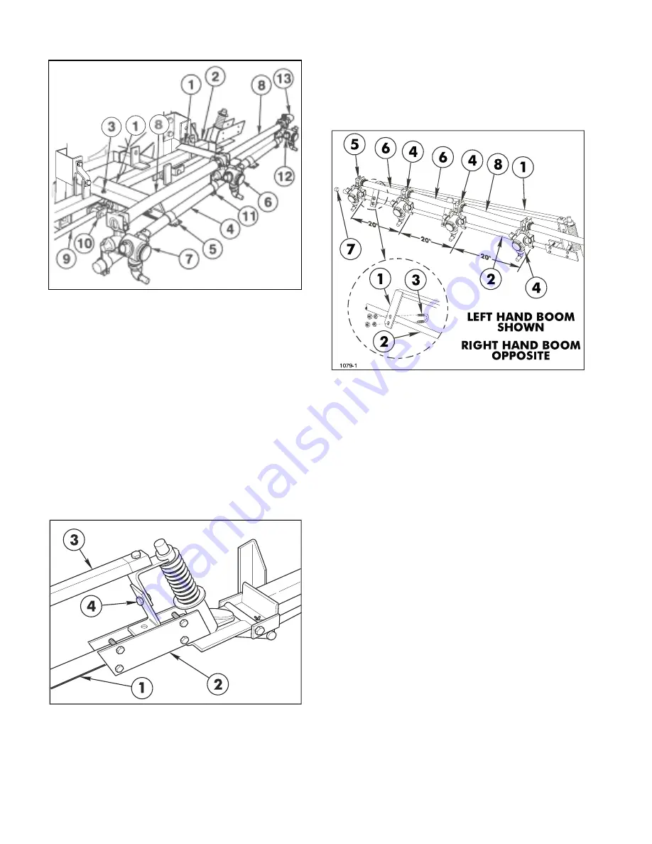
1. Extension Boom Pipe
2. Pivot ASM
FIG. 7
SETUP INSTRUCTIONS
3. Boom Support ASM
4. Height Adjustment
18.
Assemble the RH Boom Support Assembly
to the other Extension Boom Pipe.
19.
Adjust the Booms to a level position by
adjusting the jam nuts on the adustable clevis
assemblies (See FIG. 6) to the desired position,
then tighten the nuts against the Main Frame
plate.
20.
Attach three (3) Double Barb Turret Bodies
and one (1) Single Barb Turret Body with Clamp
Assemblies on each Extension Boom Pipe as
shown in FIG. 8.
1. Boom Support ASM
2. Extension Boom Pipe
3. U-bolt
4. Double Barb Turret
FIG. 8
5. Single Barb Turret
6. Jumper Hose 3/4" x 19"
7. Boom Cap
8. Jumper Hose 3/4" x 21"
21.
Level Nozzles and space 20" apart. Connect
the Turret Body Assemblies with 3/4" x 19" Jumper
Hoses and a 3/4" x 21" Jumper Hose. Secure
with hose clamps. (See FIG. 8)
22.
Route wiring harness across rear of vehicle
and secure to Valve Mounting Bar with Tie Straps.
(See FIG. 9, page 15)
15.
Insert the plugged end of an Extension Boom
Pipe into the Pivot Assembly and secure with four
(4) 1/4" x 1-1/4" cap screws and lock nuts (See
FIG. 7). Repeat on the opposite side to assemble
the other Extension Boom.
16.
Attach the LH Boom Support Assembly to
the Pivot Assembly, using a 5/16" x 1-1/2" cap
screw and lock nut. (See FIG. 7 & 8 )
17.
Secure the two (2) plates of the Boom
Support Assembly to the Extension Boom Pipe,
using two (2) 1/4" U-bolts, four (4) lock nuts and
flat washers. (See FIG. 8)
NOTE: If the optional "Foam Marker Kit" is to
be installed, refer to the instructions furnished
with that kit before proceeding to Step 15.
IMPORTANT! DO NOT over-tighten the nuts
in Steps 15 and 17. The clamping action could
crush the Boom Pipe.
1. Center Boom Angle
2. Main Frame
3. U-bolt
4. Center Boom Pipe
5. Boom Clamp
6. Double Barb Turret
7. Single Barb Turret
FIG. 6
8. Jumper Hose
9. Strut ASM
10. Adjustable Clevis
11. Turret Body Clamp
12. Threaded Barb Turret
13. 90° Hose Barb
1800
Summary of Contents for 41106-220000101
Page 49: ...49 NOTES...
Page 63: ...63 NOTES...
Page 73: ...73 SPRAY SYSTEM FLOW DIAGRAM SPYSYT 2...
Page 81: ...81 NOTES...
Page 82: ...82 NOTES...
Page 83: ...83 NOTES...


