


Touch it to set the compressor for the selected channel. Release sets the length of
time the compressor takes to return to its normal gain once the signal level drops
below the threshold. Release can be set from 10 to 1,000 milliseconds.
Touch it to set the compression ratio for the selected channel. The ratio determines
the amount of gain reduction. For example, a ratio of 4:1 means that if input level
is 4 dB over the threshold, the output signal level will be 1 dB over the threshold.
The ratio can be set from 10:1 to 1:1 until limit.
The compressor grid shows level setting of
threshold in real time.
Meter on the left indicates the input signal’s
level activity.
Meter on the right indicates degree of
compressor.
DSP Control
Level
LIMIT
(dB)
16
12
7
3
-1
-5
-10
-14
-18
-22
-26
-30
(dB)
4
8
13
17
21
25
30
34
38
42
46
50
CLIP
10
7
4
2
0
-2
-4
-7
-10
-20
-30
Release
100mS
Comp Ratio
1:1
Touch anyone of these controls to enter corresponding page.
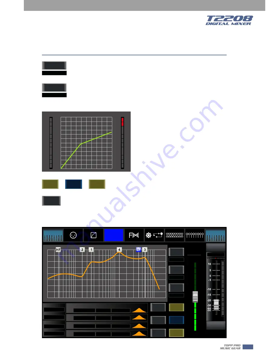
6.7 PEQ interface
It is the same with that in Assign interface in section 6.3.
Note: you can also rename the selected channel by long pressing CHXX.
Select
Channel
Save
Load
Copy
Channel
Solo
Mute
CH08
Parameter
Aux 1
-10.5dB
1.0KHz
Frequency
3.0
Q
-2.0dB
Gain
Load
Save
OFF
Flat EQ
HPF
LPF
Frequency
Frequency
Type
Type
Q
Gain
Type
EQ1
Frequency
EQ2
EQ3
EQ4
200Hz
200Hz
BW24
BW24
200Hz
1.0KHz
5.0KHz
10.0KHz
3.0
3.0
3.0
3.0
0.0dB
0.0dB
0.0dB
0.0dB
+24
+18
+12
+6
0 dB
-12
-24
-18
-6
20Hz
50
100
200
500
1K
2K
5K
10K
20K
Select
Channel
Copy
Channel
-10.5dB
CH08
Bank Select
Left
Bank Select
Right
Long
Faders
All Faders
DCA
Assign
Channel
Gate
Comp
PEQ
GEQ
FX 1
FX 2
Routing
System
EQ
29
6
Summary of Contents for T2208
Page 1: ...16 mic preamplifiers with dedicated trim control T2208 Volume...
Page 2: ...2...
Page 44: ...Hookup Diagram 44 7...
Page 45: ...Technical information 45 8...
Page 46: ...Block Diagram 46 9...
Page 47: ...Guarantee 47 10...
Page 48: ...Notes 11 48...
Page 49: ...Notes 49 11...
Page 50: ...Notes 11 50...
Page 51: ...Notes 51 11...
Page 52: ......