


49
1.7.4 Status Bar
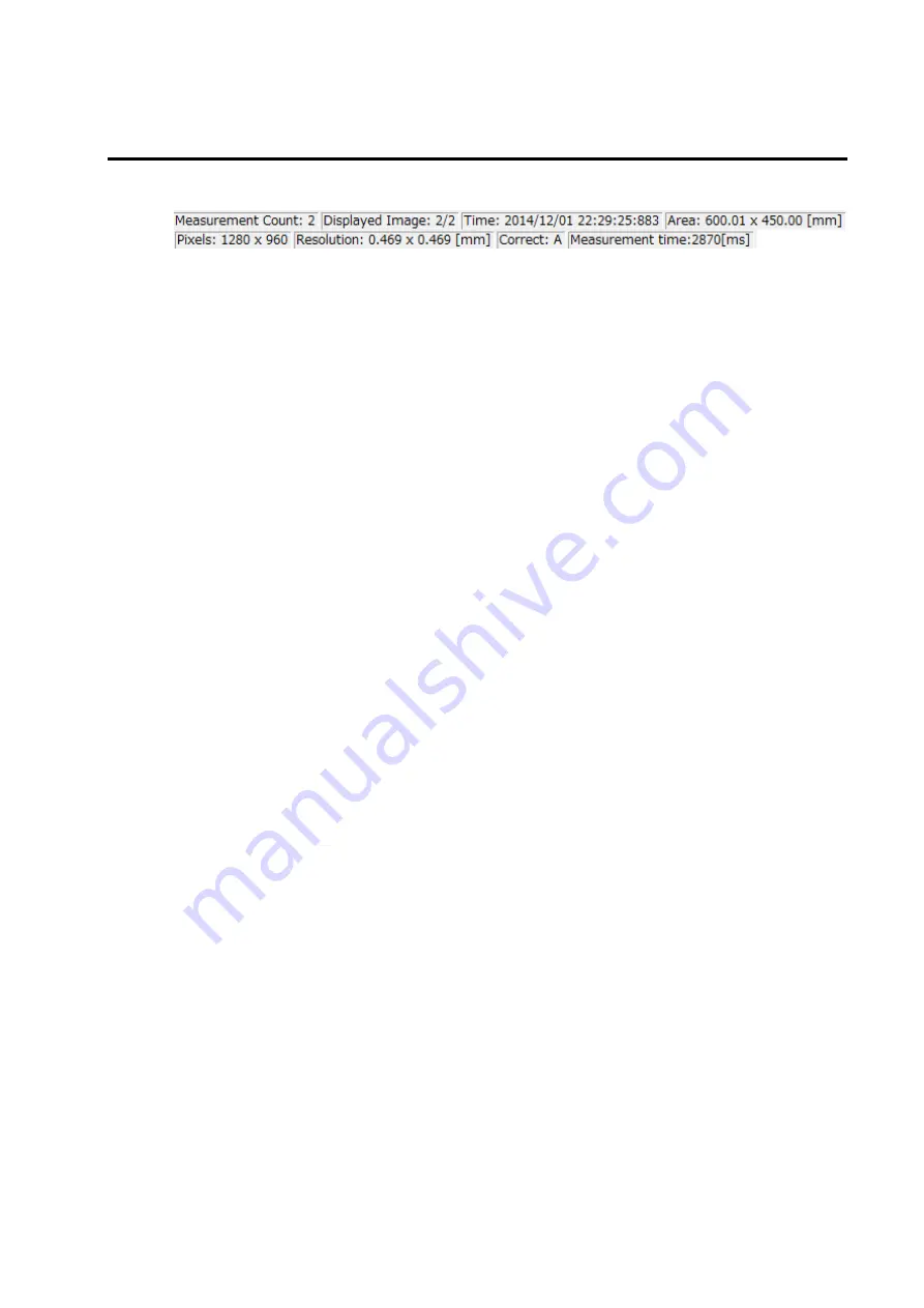
The Status bar always display the information related to the Measurement Image.
The measurement image information displayed on the Status bar is as follows.
Measurement Count
Total number of viewable measurement image is displayed. When saved measurement
image is opened, the total number of the images including the number of the opened
measurement images will be displayed.
Displayed Image
Displayed measurement image number is displayed.
The displayed image number corresponds to the number displayed by [Thumbnail View]. The
display format is as follows.
Measurement image number / number of measurement images
Time
The measurement starting time for the displayed measurement image is displayed. The
display format is as follows.
Year/Month/Date
Hour/Minute/Second/millisecond
Area
Measurable maximum area for the displayed measurement image is displayed in units of
[mm] in height and width. The measurement area is calculated based on measurement
distance and lens field angle.
Pixels
The fineness of the displayed measurement image is displayed in units of [pixel] in height and
width.
Resolution
Size per 1 [pixel] of the displayed measurement image is displayed in units of [mm] in height
and width.
Correct
Character indicates the type of current correction factor status.
Each character means as follows
Color correction or Reference color correction
:
”C”
Spot correction
:
”S”
Area correction
:
”A”
Diagonal correction
:
”D”
Filter correction
:
”F”
When all correction type are enabled, ”CSADF” appears. When correction type aren’t enable
at all, ”no” appears.
Summary of Contents for UA-10 Series
Page 2: ......
Page 19: ...17 14 5 14 5 22 12 1 4 20 UNC NUT 1004 5 6 Screw 2x5 FW x4 Screw 2x10 FW x4 7 8...
Page 134: ...132 UA 200 series 5 The Finish window is displayed Click Finish...
Page 164: ...162 4 Measured image in corrected rectangle shape will be displayed...
Page 201: ...199 2 Live View is opened...
Page 208: ...206...
Page 210: ...208 Rectangular marker area is displayed...
Page 212: ...210 3 Rectangular marker will appear...
Page 215: ...213 3 Optimization area is displayed...
Page 217: ...215 3 Optimization area is displayed...
Page 222: ...220 3 Enlarged display window appears...
Page 303: ...301 3 All the split spots are deselected...
Page 343: ...341 3 Only the center measurement spot is set All the other measurement spots are deselected...
Page 363: ...361 3 The Contour Property is displayed...
Page 374: ...372 2 The Chromaticity Diagram View is opened...
Page 380: ...378 4 Selecting 10nm Pitch displays the following view...
Page 384: ...382 4 The view returns to the original display...
Page 386: ...384 4 When Color ON is selected the Chromaticity diagram is colored...
Page 388: ...386 4 When Color OFF is selected the Chromaticity diagram is display with monotone...
Page 394: ...392 By drawing area and or child area cotinuouly overlayed areas will be built...
Page 402: ...400 4 The Chromaticity Diagram View Property is displayed...
Page 408: ...406 2 The Histogram View is opened...
Page 412: ...410 2 The Thumbnail View is opened...
Page 420: ...418 3 Scale Setting dialog will open You can change display scale of L a b view...
Page 432: ...430 3 Scale Setting dialog will open You can set scale values by key...
Page 448: ...446 3 The Time series Graph is displayed...
Page 451: ...449 Time series Measurement Random Spot List...
Page 456: ...454 4 The Pop up menu will open Select the Zoom ON 5 The specified area is enlarged...
Page 458: ...456 4 The zoomed in area returns to the original display...
Page 464: ...462 When Apply is pressed after changing the property scale the scale range is changed...
Page 495: ...493 2 From the Menu bar select Window Tile sequentially 3 The displayed views are organized...
Page 497: ...495 2 From the Menu bar select Window Close All sequentially...
Page 500: ...498 View mode UA 10 Series UA 200 Series...
Page 507: ...505 UA 200A...
Page 522: ...520 External Dimension Diagram UA 10 series Main body with Tripod screw adapter...
Page 523: ...521 Depth5 Main body with Tripod screw adapter and Spacer Mount...
Page 524: ...522 UA 200 series UA 200S UA 200AS...
Page 525: ...523 UA 200WS UA 200AWS...
Page 526: ...524 UA 200T UA 200AT...


