


- 20 -
2.5 Measuring
with the SR-LEDW/SR-UL2/SR-UL1R/SR-3AR
Examples of measurements are introduced in this section for reference.
2.5.1 Measuring Directional Light Sources
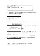
When measuring an LED or other directive or uneven light source, use a white board as shown in the
figure. A direct observation may result in irreproducible data.
2.5.2 Measuring Very Small Surfaces
For measuring smaller area than the specification of SR-LEDW/SR-UL2/SR-UL1R/SR-3AR, one of the
optional attachment lens is available. The two attachment lenses are the AL-6 and the AL-11.
SR-LEDW/SR-UL2/SR-UL1R/SR-3AR Measurement Diameter
☞
6
‘Appendix: Specifications and
Performance’
The attachment lens can be screwed onto the end of the SR-LEDW/SR-UL2/SR-UL1R/SR-3AR
objective lens.
When using an attachment lens, a correction factor must be set on SR-LEDW/SR-UL2/SR-UL1R/SR-
3AR.
Setting a Correction Factor
☞
‘3.11 Using a Correction Factor’, '3.12 Displaying and Editing the
Correction Factor'
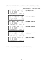
The measuring field will affect the measurement diameter.
For the AL-6
For the AL-11
Measuring field
Measurement Dia.(mm)
2°
2.00
– 2.88
1°
1.00
– 1.44
0.2°
0.20
– 0.29
.1°
0.10
– 0.14
*
Measurement distance from metal edge : For the AL-6: 51.72 to 68.53 mm
For the AL-11: 19.56 to 24.80 mm
Measuring field
Measurement Dia.(mm)
2°
1.18
– 1.53
1°
0.59
– 0.76
0.2°
0.19
– 0.15
0.1°
0.06
– 0.08
Light source
White board
SR-UL2/SR-UL1R/SR-3AR
Luminance = Measurement value Lv × Luminance factor


