background image

CA-200F Corneal Analyser - Rev. 7  16/01/2012 

 19 


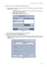
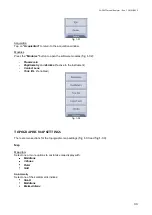
fig. 1-1 


You  can  insert  a  new  patient  or  select  an  existing  patient  from  the  database  of  the  PC  connected  to  the 
analyser. 
 
To  insert  a  new  patient, fill  in  the  patient  details  fields  using  the on-screen  keyboard.  If  you  need  to  insert 
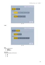
special characters, keep pressing the letter buttons: a panel with the choice of the possible characters for the 
selected letter will appear (example 

fig. 1-2

).  

Press the 

“Open”

 button to access the acquisition window for the patient just inserted. 


fig. 1-2


There are two ways to select an existing patient from the database of the PC:  


Type in  the patient’s name  or surname or part  of them and press the 

“DB List”

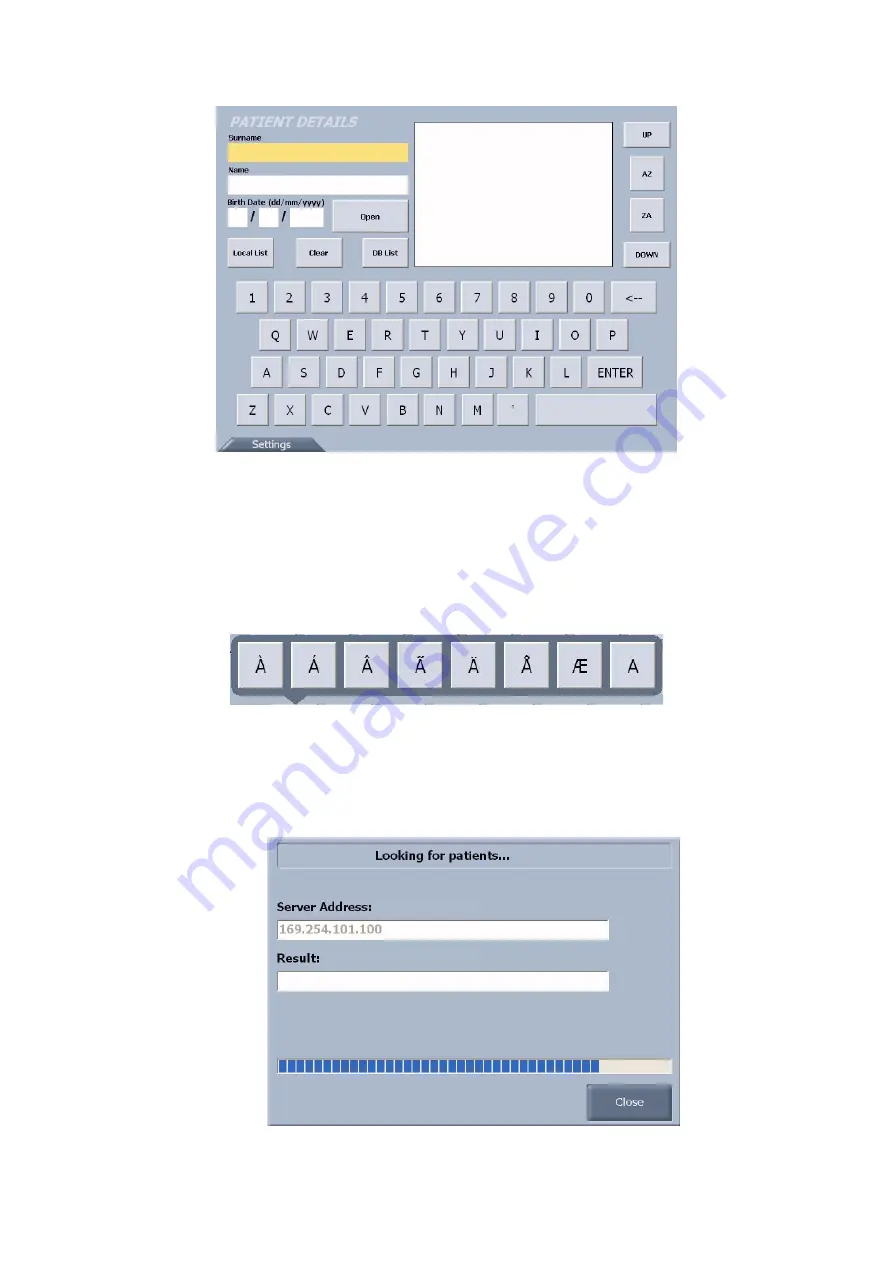
  button  to  open  a 

dialogue window with the PC (

fig. 1-3

).  


fig. 1-3 
Summary of Contents for CA-200F

Page 1: ...INSTRUCTIONS FOR USE CORNEAL ANALYSER CA 200F CORNEAL ANALYSER 0051 REV 7 2012...

Page 2: ...r is installed in rooms for medical use and is not connected to a computer there is no need to use an insulated transformer If a printer is connected directly to the CA 200F corneal analyser it must b...

Page 3: ...the cornea From the topographic map data a set of parameter indices are processed for the measurements The main applications of the corneal analyser are the following Cornea measurements for diagnost...

Page 4: ...market The instrument analyzes any type of corneal map axial instantaneous with 2D representation This instrument also allows you to simulate contact lenses and view the 3D map to analyze the wavefron...

Page 5: ...n increased emissions and reduce the immunity of the device or system The device must not be used in contact with other equipment If it is inevitable to use the device in contact with other instrument...

Page 6: ...61000 4 5 1kV differential mode 1kV differential mode The quality of the power mains should be that of a typical commercial or hospital environment Voltage dips short interruptions and voltage variat...

Page 7: ...erence may occur in the vicinity of equipment marked with the following symbol Recommended separation distances between portable and mobile RF communications equipment and the surgical Navigation devi...

Page 8: ...ARNING CONSULT THE ATTACHED DOCUMENTATION ISO 7000 1641 OPERATING INSTRUCTIONS CLASS 1 LED PRODUCT IN ACCORDANCE WITH EN 60825 1 This symbol applies solely to EU member states With the aim of preventi...

Page 9: ...ovides a description of the safety warning labels and plates on the instrument body Carefully read the following PRECAUTIONS and SAFETY RULES as well as the manual and observe the instructions contain...

Page 10: ...turer is not responsible for damage caused by fire earthquakes actions by third parties and other accidents or negligence and abuse of the instrument by the user in unusual conditions The manufacturer...

Page 11: ...of safety warning labels and plates on the instrument body Carefully read the following PRECAUTIONS and SAFETY RULES as well as the manual and observe the instructions contained therein WARNING To pr...

Page 12: ...ction 17 Connection to an existing network 17 1 BASIC OPERATIONS 18 GENERAL DESCRIPTION 18 ACQUISITION 18 ACQUISITION WHEN CONNECTED TO A PC 18 ACQUISITION IN STAND ALONE MODE 27 TOPOGRAPHIC MAP 29 TO...

Page 13: ...CA 200F Corneal Analyser Rev 7 16 01 2012 13 COMPONENTS MAIN COMPONENT PARTS Placido disc Power connector Display USB port LAN port Acquisition button Joystick Function buttons ON OFF button...

Page 14: ...CA 200F Corneal Analyser Rev 7 16 01 2012 14 CONTROL PANEL COMPONENTS Touch screen display Function buttons...

Page 15: ...2012 15 CA 200F STANDARD ACCESSORIES The following accessories are included in the package TOUCH SCREEN PEN USB EXTENSION CABLE INSTRUCTION AND ASSEMBLY MANUAL DECLARATION OF CONFORMITY CALIBRATION TE...

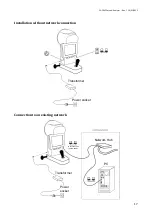
Page 16: ...ON Hardware installation point to point network configuration Software installation See CA Series Installation Manual included in the CA 200F Setup CD Chinrest Sliding plate Transformer Table Power so...

Page 17: ...F Corneal Analyser Rev 7 16 01 2012 17 Installation without network connection Connection to an existing network Transformer Power socket Power socket Transformer LAN connection paired cable Network H...

Page 18: ...ike analysis information on the optical properties of the cornea and the optical problems that may disturb sight Contact lens simulation the software selects from a database the lens best suited to th...

Page 19: ...insert special characters keep pressing the letter buttons a panel with the choice of the possible characters for the selected letter will appear example fig 1 2 Press the Open button to access the ac...

Page 20: ...d press the Open button or double tap on the patient s name to access the acquisition window If the communication between the PC and the device is not correctly established see the Troubleshooting sec...

Page 21: ...fer problems see the Troubleshooting section Close closes the dialogue window Delete Selected deletes the selected files fig 1 6 Clear clears the contents of the list and the patient details fields AZ...

Page 22: ...The following buttons are available in the acquisition window R and L indicates the eye being acquired highlighted in yellow TOPO PUPI FLUO indicates the type of acquisition highlighted in yellow you...

Page 23: ...the Settings section Close Save Tap on Close Save to open the options fig 1 12 Store Locally locally stores the data acquired This data can be sent to the PC using the Local List button in the Patient...

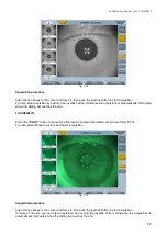
Page 24: ...Move the instrument forward and backward following the indications of the red and blue arrows on the screen to find the best focus the system will automatically capture the image To manually acquire...

Page 25: ...hen the sliding bar reaches the end FLUORESCEIN Press the FLUO button to access the fluorescein analysis acquisition environment fig 1 15 You can select between picture and movie acquisition fig 1 15...

Page 26: ...eyboard layout select the desired layout and press Set as current layout Pressing the Close button you can see the change in keyboard layout in the Patient Details window fig 1 16 Acquisition Settings...

Page 27: ...STAND ALONE MODE To use the instrument in stand alone mode the PC Link software module must be deactivated The acquisition environment is as shown in fig 1 18 fig 1 18 Tapping on the New Patient butt...

Page 28: ...t button changes to Close fig 1 20 Tapping on Close the patient data and the gallery are deleted The Close button changes back to New Patient and then you can insert a new patient fig 1 20 All the oth...

Page 29: ...o view the map of the right eye R or the left eye L In the map window you can select the following buttons fig 1 22 Axl or Tan axial or tangential map Abs or Nor absolute or normalized scale Eye Map R...

Page 30: ...n the button to open the panel fig 1 25 where you can select with the arrow buttons other meridians along which to view the curvature profile fig 1 25 Select the button to close the panel and update t...

Page 31: ...n to view the keratorefractive indices fig 1 28 3 and 5 mm astigmatism Average pupillar power for a 4 5 mm pupil Asphericity of an 8mm diameter cornea Longitudinal spherical aberration of a 4 5 mm dia...

Page 32: ...n suspected keratoconus yellow topography compatible with keratoconus red If the topography is compatible with keratoconus or indicates suspected keratoconus the numerical values of the geometrical co...

Page 33: ...Fluorescein Pupillometry and Zernike if active in the instrument Contact Lens Toric IOL if enabled fig 1 32 TOPOGRAPHIC MAP SETTINGS There are two sections for the topographic map settings fig 1 33 a...

Page 34: ...CA 200F Corneal Analyser Rev 7 16 01 2012 34 fig 1 33 Scales fig 1 34 Map Select a unit of measure Diopters Millimeters Asphericity Select an asphericity unit of measure e SF p Q...

Page 35: ...t acquisition in the gallery is displayed in the main window Tapping on a picture it is displayed in the main window Tapping on a movie it automatically starts playing fig 1 36 Using the buttons below...

Page 36: ...SB printer Acquisition Returns to the acquisition window Close Tapping on the Close button the system returns to the topographic map environment if you have also acquired topographies in the same sess...

Page 37: ...eye You can select the sequence of images to be displayed using the following buttons fig 1 40 fig 1 40 D Dynamic P Photopic S Scotopic M Mesopic Only the buttons for the acquisition done are active D...

Page 38: ...the main window there are buttons that allow you to view all the frames in sequence go forward or back by one frame or return to the first frame There are also two numbers that indicate the number of...

Page 39: ...um and maximum values of the pupil diameter acquired in dynamic pupillometry and the pupil center Cartesian and polar coordinates Latency fig 1 45 The graph shows the acquisition time in seconds on th...

Page 40: ...epresents the statistical percentile value of the sample for each acquisition in controlled light conditions As indicated in the legend on the right hand side and the values shown on the left the red...

Page 41: ...ig 1 47 fig 1 48 Select one or more options to customize the display of the pupil images fig 1 47 and fig 1 48 with Grid Ruler Ring Center the center of the pupil will be displayed in blue and the fix...

Page 42: ...ial Primary aberration maps Astigmatism shows the map the entity of diopters the axis and the RMS value Spherical aberration shows the map the amount of longitudinal spherical aberration in diopters a...

Page 43: ...an select the pupil diameter in a range between 2 mm and 7 5 mm to see how the aberrations change as the pupil diameter changes fig 1 51 Report Save the report as a PDF file to a USB unit or print it...

Page 44: ...e Selecting a lens You can select a lens from the database by tapping on the menu on the optical bar fig 1 53 fig 1 53 Brand Press the Brand button to select a brand fig 1 54 The best lens in the manu...

Page 45: ...ymal film profile under the lens selected fig 1 58 fig 1 58 Tap on the button to open the panel fig 1 59 where you can select with the arrow buttons other meridians along which to view the lachrymal f...

Page 46: ...Pref Lens preferences Refraction Shows the refraction values fig 1 61 Tap on to set the refraction values fig 1 62 Use the arrow buttons to set the individual values Select the button to close the pa...

Page 47: ...n Decentration Drags the lens to the desired position The Reset button resets the initial lens position Lens preferences Tap on the Pref button to open the lens preferences window fig 1 65 fig 1 65 Yo...

Page 48: ...INGS Manufacturers fig 1 66 Allows managing your own lens database A brand list is displayed on the left hand side fig 1 66 Tap on the Import button to add new manufacturers to the database You can im...

Page 49: ...CA 200F Corneal Analyser Rev 7 16 01 2012 49 Lenses fig 1 67 Set the apical clearance using the up down arrows fig 1 67...

Page 50: ...ocular lenses fig 1 68 The initial window fig 1 68 shows the summary of the cornea diagnosis with all the information on corneal regularity symmetry and keratoconus screening Tap on the R and L button...

Page 51: ...t Tap on Details for the surgeon details fig 1 70 Tap on Add new to add a new surgeon fig 1 70 Tap on Close to close the surgeon details Tap on Delete to delete the surgeon data Tap on Save to save th...

Page 52: ...stigmatism Incision Location Tap on Calculate IOL to view the result window with the pre op and post op information fig 1 72 fig 1 72 Tap on Order Form to print the report on a connected USB printer o...

Page 53: ...en drive in the CA 200F device Tap on the Upgrade button The system will be restarted for the first time Disconnect the USB pen otherwise the system will not be started Access the Admin Tools menu aga...

Page 54: ...he PC Use the Test button to test the network to check that the connection has been established fig 1 76 If there are no known clients in the search list tapping on the DB List button the network sett...

Page 55: ...the update package in the root main folder of an empty and FAT32 formatted USB pen drive Press the Module Update button Software Modules The Toric IOL and PC Link modules are software modules that nee...

Page 56: ...TION See the CA Series Installation Manual included in the Setup CD CA 200F PC SOFTWARE SETTINGS For details refer to the Corneal Analyser Software Manual To open the settings window in the main Corne...

Page 57: ...v 7 16 01 2012 57 fig 2 2 To select the acquisition device tap on Corneal Analyser select CA 200F as instrument and press Ok to close the window and save the changes Tap on Cancel to close the window...

Page 58: ...that the PC is on and that the Wi Fi or LAN connection is active Check that the IP address for connection to the PC has been set correctly The calibration check has failed Repeat the measurement and...

Page 59: ...00F Corneal Analyser Rev 7 16 01 2012 59 4 REFERENCES Default accessories Optional accessories CA 100 200 chinrest CA 200 clens CA 200 caldev CA 100 200 baseplate CA 100 200 baseplate no chinrest poss...

Page 60: ...idity 30 75 no condensate Atmospheric pressure 700 1060 hPa Storage Temperature 10 40 C Relative humidity 30 75 no condensate Atmospheric pressure 700 1060 hPa Electrical specifications Power source A...

Page 61: ...other patient clean and disinfect the supports that come into contact with the forehead and chin with neutral detergents Calibration check It is absolutely necessary to test the calibration when the i...

Page 62: ...ven at the bottom of the window acquire the sphere eight times with a radius of 8 mm If the calibration is correct a window will appear with the message Calibration Check POSITIVE If the test has a ne...

Reviews: