❏
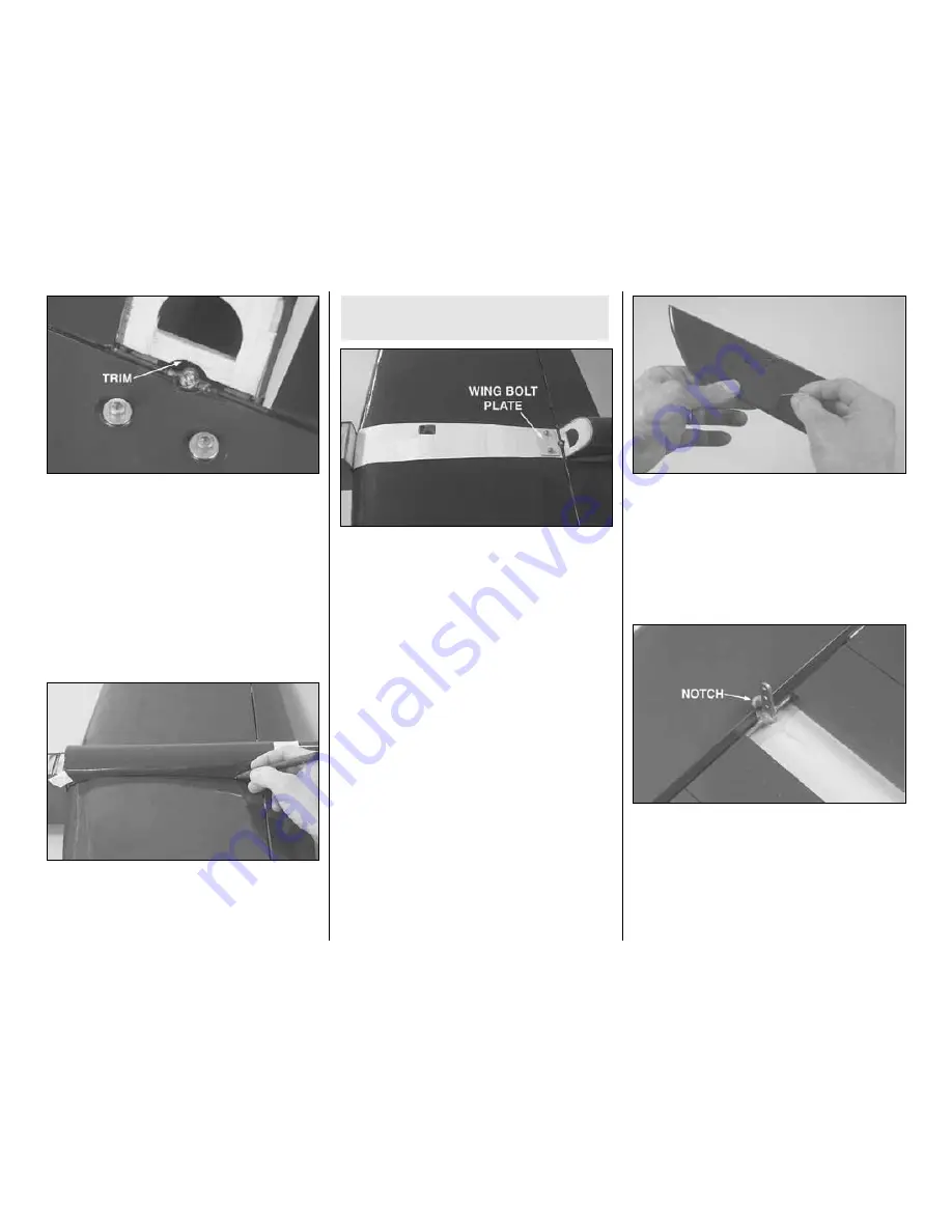
3. Remove the belly pan from the bottom of the
fuselage. Temporarily bolt the wing to the fuselage
with two 4-40 x 1-1/2" [38mm] screws and #4
washers. Trim the balsa cross brace as necessary
to accommodate the solder joint holding the control
horn to the flap joiner wire.
❏
4. Place the belly pan on the bottom of the wing in
alignment with the fuselage. Tape the belly pan into
position. Use a fine-point felt-tip pen to mark the
outline of the belly pan onto the bottom of the wing.
Mark the fuselage sides on the top of the wing.
❏
5. Remove the belly pan and wing. Use a sharp,
new knife blade or a heated soldering iron to cut the
covering from the wing 1/16" [2mm] inside the lines.
If using a knife, use a light touch and great care not
to cut into the sheeting under the covering or the
wing will be weakened. Using a soldering iron is
preferred because it melts through the covering
without cutting into the wood. Move the soldering iron
fast enough to melt through the covering without
burning the wood. After cutting the covering use
denatured alcohol and a tissue to clean the ink lines
from the covering. Then, peel off the covering.
❏
6. Center the 1" x 1-1/2" [26 x 38mm] plywood
wing bolt plate over the holes on the bottom of the
wing. Glue the plate into position. Using the holes in
the top of the wing as a guide, drill 9/64" [3.6mm] (or
1/8" [3.2mm]) holes through the plate. Bolt the wing
onto the fuselage.
ASSEMBLE THE FUSELAGE
Prepare the Stab
❏
1. Examine the stab and elevators and determine
which side looks best. Use a felt-tip pen to write “top”
on the side that looks best.
❏
2. Separate the elevators from the stab by peeling
off the tape. Use a pin to poke three or four holes
along one side of all the “ribs” in the bottom of the
stab and elevators. These holes will allow expanded
air to escape while tightening the covering.
❏
3. Use a covering iron to tighten the covering on
the stab and elevators.
❏
4. The same as was done with the wing and flaps,
prepare the elevators and stab for the hinges by
enlarging the slots if necessary, test fitting the hinges
and cutting “V” notches in the elevators to
accommodate the hinge pins. Also prepare the
elevators for the joiner wire. Trim the trailing edge of
the stab as necessary to accommodate the solder
joint on the joiner wire. “Tweak” the joiner wire as
necessary to align the elevators with each other.
Refer to this photo for the following
two steps.
- 10 -


