2700-4001_22 IMA Manual
23
Last Revision: 12/14/2021
Tapped Hole Mounts Recommended Torque
Front / Rear / Side Mount Holes
M6
3 N-m
M8
30 N-m
M12
85 N-m
2 ft-lb
22 ft-lb
63 ft-lb
Table 4.2: Tapped hole torque recommendations
Mounting Plate (MP2) Clearance Hole Bolt and Torque Requirements (Minimum Fastener
Grade 8.8)
M8
11 N-m
M10
30 N-m
M14
100 N-m
(IMA22) 8 ft-lb
(IMA 33/44) 22 ft-lb
(IMA55) 74 ft-lb
Table 4.3: Mounting Plate (MP2) Clearance Hole Bolt and Torque Requirements (Minimum Fastener Grade 8.8)
Front Flange Mount (FFG) Clearance Hole Bolt and Torque Requirements (Minimum Fastener Grade 8.8)
M8
11 N-m M12
26 N-m
M14
100 N-m
M16
115 N-m
(IMA22) 8 ft-lb
(IMA33)
19 ft-lb
(IMA44) 74 ft-lb
(IMA55) 85 ft-lb
Table 4.4: Front Flange Mount (FFG) Clearance Hole Bolt and Torque Requirements (Minimum Fastener Grade
8.8)
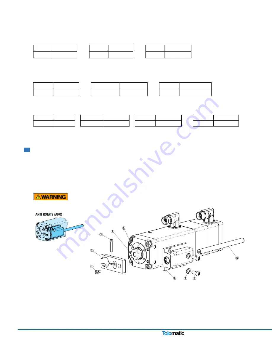
4.5 Field Installation of ARO (Anti Rotation) Option
The design of the IMA actuator allows the extending rod to rotate. This provides simple setup of the actuator by
allowing the user to rotate the rod and thread it in and out of the actuator for mechanical attachment or system
testing. This feature also requires that the rod be kept from rotating when used in its dedicated application to insure
proper linear motion. In most applications, such as those where the load is coupled to linear bearings, or some
other support device, the load cannot rotate, and thus provides anti-rotation for the extending rod of the actuator.
For applications in which the load is free to rotate, Tolomatic offers the anti-rotation systems shown below.
The anti-rotate option (ARO) is not a guide or support mechanism. It is intended only as an anti-rotate device.
Figure 4.6: View of ARO (Anti Rotate Option)
ARO ATTACHMENT PROCEDURE / GUIDELINES
Recommended tools: 4, 5, 6 and 10 mm hex keys (allen wrenches), small dead-blow hammer.


