2700-4001_22 IMA Manual
20
Last Revision: 12/14/2021
working mass should the drive screw fail. Uncontrolled moving masses can cause injury or damage to property. If
the screw drive fails, due to wear or excessive load, gravity may cause the working mass to drop.
For bench or fixture setup and testing of Tolomatic IMA Actuators, the actuator thrust rod must be anti-rotated by a
fixture and the actuator securely retained to the bench or fixture. Never use a hand held wrench/device to provide
the anti-rotate function while the motor is powered as contact with the internal end of stroke may send the
wrench/device flying and may harm the operator or damage the actuator.
4.4.1 Alignment
Alignment of the actuator with respect to the application load and axis of motion is essential to minimize side
loading. The IMA is not meant to be used in applications where side loading occurs as side loading will reduce the
life of the actuator and rod seals.
4.4.2 Side Load Considerations
Excessive side load on the output thrust rod of the actuator will dramatically reduce the life of the actuator and
should be avoided. Side load can be caused from misalignment or loading that is not inline with the actuator output
thrust rod.
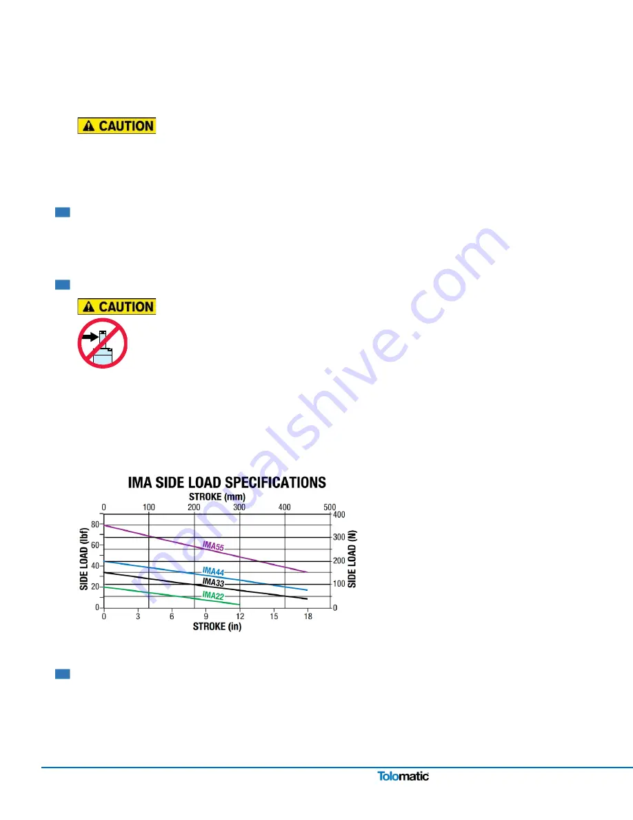
The graph shows the maximum side load values for the Tolomatic IMA Actuators. Measures shall be established to
limit any side loading that exceeds these values.
For maximum service life, external guiding is recommended to minimize side loading to the thrust rod and provide
consistent alignment throughout service life.
Figure 4.2: Side load must not exceed maximum values represented by the lines in the graph
4.5 Mechanical Installation Instructions
1.
Remove packaging
2.
Carefully remove linear actuator from package. *Consider the weight of the actuator. Depending on the
configuration, the actuator can weight up to approximately 42 kg (92.6 lb)


