Tolomatic User Guide:
IMA-S Integrated Motor Rod-Style Actuator - Stainless Steel
• 29 •
6 .1 Homing
When homing the IMA-S avoid excessive force (120% Continuous Stall Force Maximum). During
homing do not exceed speeds of 0.39 in/sec (10 mm/sec). The IMA-S is designed with internal
bumpers, however, exceeding these recommendations can cause permanent damage to the actuator.
Careful attention should always be taken to prevent exceeding the physical limits of the actuator.
6 .2 Brake
Many applications benefit from the addition of the Tolomatic integral brake. Whenever the brake is
not powered the screw is prevented from turning. (Back driving under the load)
The brake is spring engaged and electrically released. The holding capacity of the brakes exceeds
the continuous stall force of the actuator.
CAUTION!
DO NOT
attempt to operate the actuator with the brake applied.
Allowing the actuator to operate with the brake applied may cause serious damage to the actuator
and/or the brake. Do not use the brake to support heavy loads while an operator is under the load.
Provide another means to lock the load in position. The brake is a spring applied friction mechanism
and does not provide a positive lock.
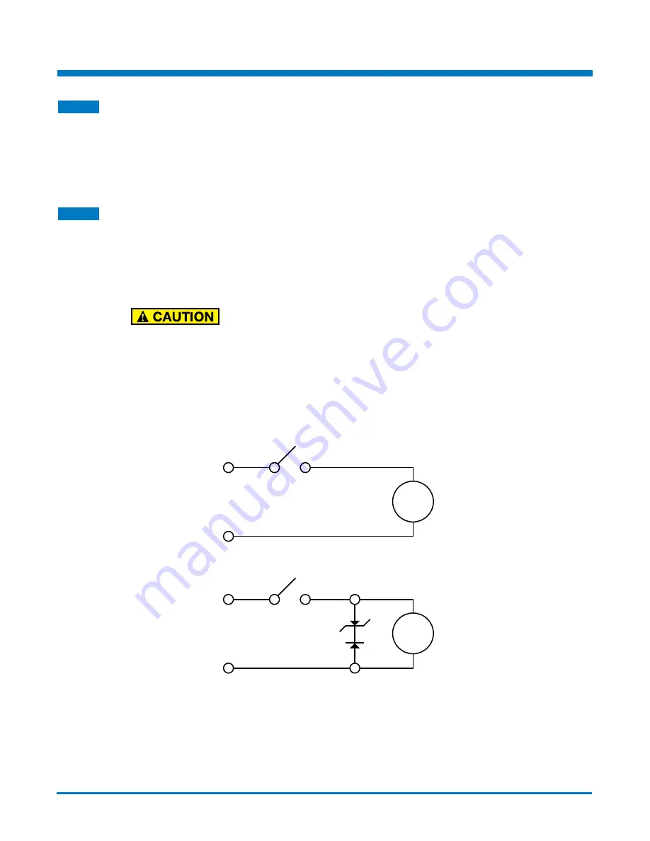
Protecting the brake from voltage transients in applications where it will be engaged and disengaged
frequently is advised. The use of a rectifying diode and zener diode will provide optimal protection
against these transients.
RED
BLACK
BRAKE
+
-
Figure 6-1: Fastest Engage / Disengage time, least protection
RED
BLACK
BRAKE
+
-
Figure 6-2: Increased Engage / Disengage time, best protection
Tolomatic strongly recommends the use of wiring best practices be used when making electrical
connections to the actuator. Too many junctions or improper shielding may result in poor performance
or render the actuator inoperable.
IMA-S Operation and Start Up Considerations
6


