


PWi Forging User’s Manual
Doc #17663 Rev A Page
Toledo Integrated Systems
70
5)
Place the Load Cells in the Correct Position in the Press
A)
All load cells should be equal distance from the sides and front and rear. For example, 12” from the
sides, 10” from front and rear. Load cells are typically placed at each corner of the press’s bed.
B)
Cycle the press without hitting the load cells first.
C)
Place cardboard on the top and bottom of the load cells.
6)
Cycle the Press
A)
While still in the Calibration menu, push
or
to display the
PEAK
tonnage
.
B)
Further adjust the shut height so that the press impacts the load cells and generates a load at 100%
of press capacity. See warning below.
WARNING
:
Depending on the press capacity and the size of the load cells being used, loading the press at capacity
with load cells could indent the ram or bolster. To prevent this situation from happening, do one of the
following:
a)
Calibrate the press only up to 80% of capacity, or
b)
Use larger load cells to increase the loading surface. For instance, to calibrate a 400 Ton
press at capacity, use (4) 250 Ton load cells instead of (4) 100 Ton load cells.
7)
Gather, Record, and Enter Data
A)
Record the load cell numbers for each of the channels. These are the load values of the press
corners.
B)
Record the peak tonnage values from the PWi Forging.
C)
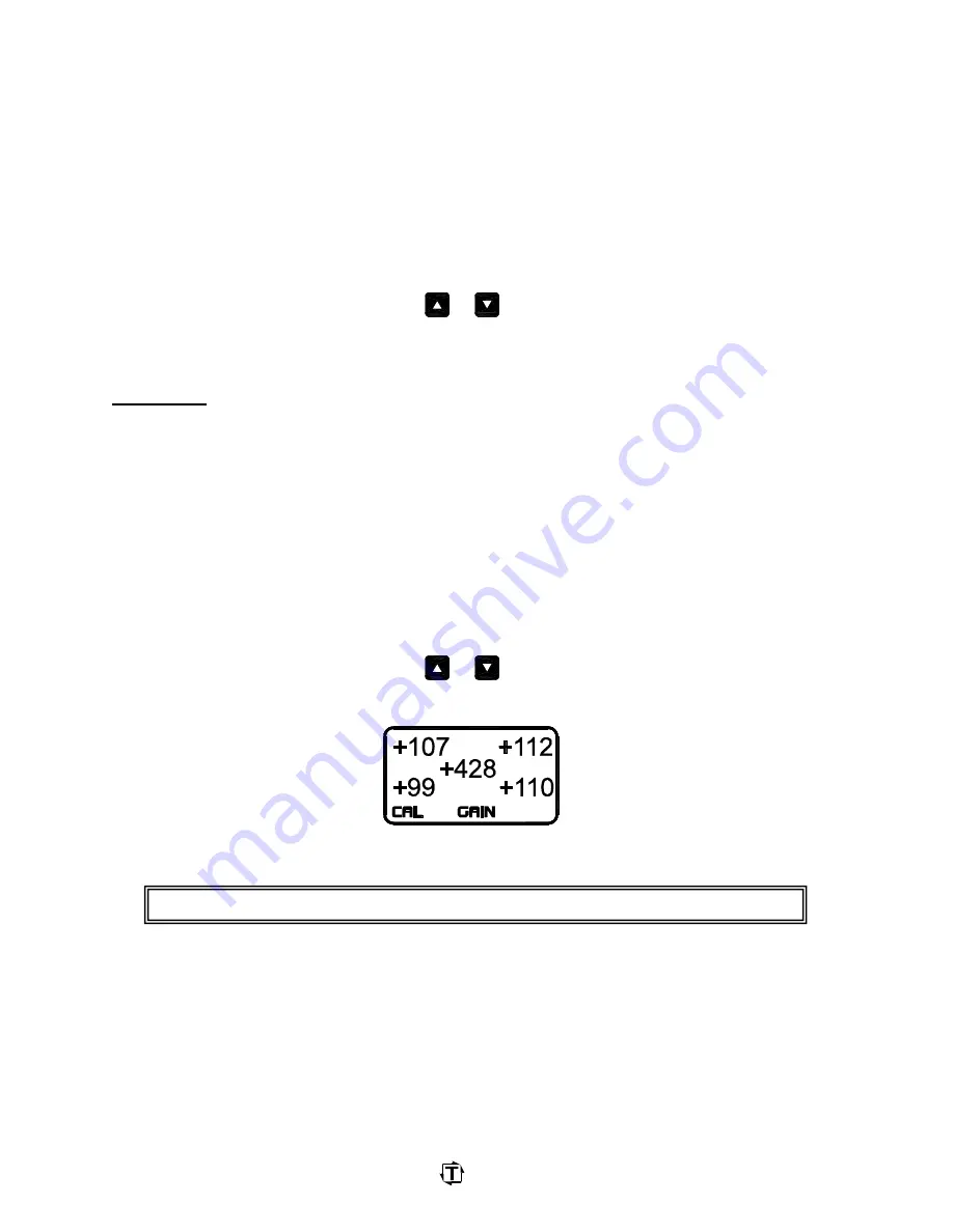
While still in the Calibration menu, push
or
to display the
GAIN
numbers. This enables
the PWi Forging’s shunt. Record the Gain numbers.
D)
Use the following formula to determine the new gain number:
E)
Repeat the calculation for each channel.
New Gain Number = (Load Cell reading ÷ Peak Tonnage reading) x Current Gain
Summary of Contents for PWi Forging
Page 1: ...17664 PWi Forging Tonnage Monitor By Toledo Integrated Systems User s Manual...
Page 2: ......
Page 28: ...PWi Forging User s Manual Doc 17663 Rev A Page Toledo Integrated Systems 26...
Page 74: ...PWi Forging User s Manual Doc 17663 Rev A Page Toledo Integrated Systems 72...
Page 78: ...PWi Forging User s Manual Doc 17663 Rev A Page Toledo Integrated Systems 76...
Page 80: ......
Page 82: ...Doc 11080 Rev A T400 INSTALLATION PAGE 2...
Page 83: ...Doc 11080 Rev A T400 INSTALLATION PAGE 3...
Page 84: ...Doc 11080 Rev A T400 INSTALLATION PAGE 4...
Page 87: ...Doc 11080 Rev A T400 INSTALLATION PAGE 7...
Page 88: ......
Page 89: ......
Page 90: ......
Page 91: ......
Page 92: ......


