


172-65608MA-03 (RGDS) 5 Oct 2021
8
Water Mixing and Separation Section
1. Make sure the piping between the injector (G) and the temperature sensors (D) is
straight and horizontal. Do not install other devices such as check valves and
strainers that could cause a pressure drop.
2. Ensure the piping between the injector (G) and the condensate separator (I) is at
a slight decline (between 1:100 and 1:200) and is of the required straight piping
distance.
Minimum required straight piping length by nominal diameter
Pipe
size/DN
mm
50
65
80
100
125
150
200
(in)
(2)
(2
1
/
2
)
(3)
(4)
(5)
(6)
(8)
Length
m
(ft)
4.5
(15)
5.5
(9)
6.5
(22)
7.5
(25)
10
(33)
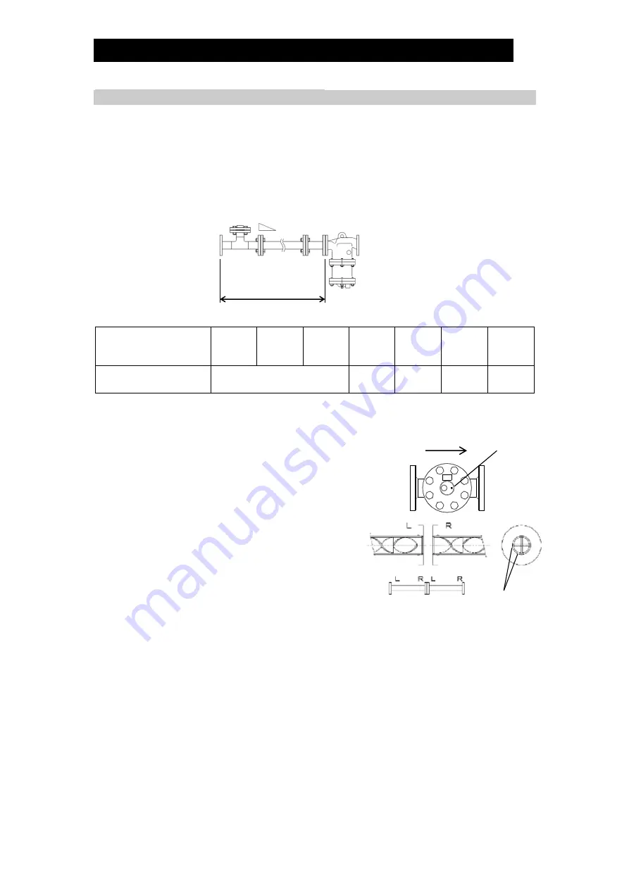
3. The injector (G) and static mixer (H) each have an installation direction.
Installation in the wrong direction will prevent the equipment from functioning as a
desuperheater.
a) There is a circular engraving on top of
the injector body (G) (see right). Make
sure this engraving is on the
downstream side of the injector when
installing the desuperheating water
piping.
b) The static mixer (H) is shipped as two
separate pipe-shaped products.
Each static mixer has a flow direction
indicated on the flange (L = Left, R =
Right). Make sure the second mixer starts
with the same direction as the first mixer, i.e.
“LR-LR” and “RL-RL”.
Note:
“L” and “R” do not denote upstream and downstream.
In addition, make sure the static mixer flange faces meet so that the internal
mixer partitions meet at right angles to each other at the flange face.
There is no restriction on the direction the mixer partitions face in the end of
the flanges on the upstream and downstream sides.
4. Ensure the steam trap (J) on the condensate outlet of the injector (I) is installed in
a location where inspections and maintenance can be performed.
Allowable inclination:
1:100 to 1:200
Required straight
piping distance
Condensate
Separator (I)
Static Mixer (H)
Water Injector (G)
Upstream
Downstream
Engraving
Mixer partitions


