background image


172-65608MA-03  (RGDS)    5  Oct  2021


5


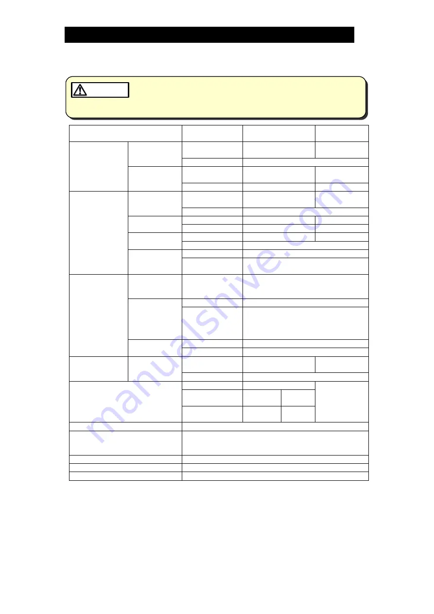
System Specifications 


Install properly and DO NOT use this system outside the recommended 

operating pressure, temperature and other specification ranges. 

Improper use may result in such hazards as damage to the system or 

malfunctions which may lead to serious accidents. Local regulations 

may restrict the use of this system to below the conditions quoted.


CAUTION 


Item 

Property 

RGDS (Standard 

Specification) 

Ex-proof 

Specification 

Pressure 
Reducing 
Section 

Steam Control 
Valve 

Model 

CV10

 1)


(Non Ex-proof) 

CV10

 1)


(Exd II BT5) 

Size/Connection  Depends on specifications 

Pressure 
Sensor 
(With Siphon) 

Model 

MBS33M

 1)


(Non Ex-proof) 

KD43

 1)


(Exd II BT4) 

Size/Connection  R 3/8 

R 1/2 

Desuperheating 
Section 

Temperature 
Control Valve 

Model 

CV10

 1)


(Non Ex-proof) 

CV10

 1)


(Exd II BT5) 

Size/Connection  Depends on specifications 

Temperature 
Sensor 

Model 

TR1-35S

 1)


R1G

 1)

 (d2G4) 

Connection 

R 3/8 

R 1/2 

Strainer 

Model 

Y3

 1)


Size/Connection  Depends on specifications 

Check Valve 

Model 

CKF3M

 1)


Connection 

Flangeless (wafer) type 
Size depends on specifications 

Water Mixing 
and Separation 
Section 

Water 
Injector, 
Static Mixer 

Size/Connection 

50 

– 200 mm (2 – 8 in): JIS 10K, 

20K, 30K, ASME/JPI Class 150, 300 

Condensate 
Separator 

Model 

DC3 

Size 

50 

– 150 mm (2 – 6 in) 

(For 200 mm (8 in) water 
injector/static mixer, 150 mm (6 in) 
separators installed in parallel) 

Steam Trap 

Model 

JS-X series, JH series 

Size/Connection  Depends on specifications 

Pump Section

 2)

  Pump 

Model 

CRN

 1)


(Non Ex-proof) 

CRN

 1)


(eG3, d2G4) 

Size/Connection  Depends on specifications 

Control Panel 

Power rating 

200 V 

Special order 

Installation 
Location 

Indoor 

Outdoor 

Installation Type  Wall-

mounted 

Stand-
alone 

Pressure Range 

0 to 1.6 MPaG (0 to 250 psig) 

Minimum Set Temperature 

C (10 

F) above saturated steam temperature 

(Size 200 mm (8 in): 10 

C (20 

F) above saturated 

steam temp.) 

Steam Supply Temp. Stability   

Within 

C (1.8 

F)

 3)


Steam Velocity 

5 to 50 m/s (20 to 160 ft/s) 

Steam Discharge 

200 to 30,000 kg/h (450 to 66,000 lb/h) 

1)

 Standard products when the components are supplied by TLV. The model type may differ 

depends on the installation environment. 

2)

 This device is required when the pressure of the desuperheating water supplied to the 

system is insufficient. 

3) 

This value depends on the status of the process as well as the PID setting and is only to be 

used as a reference. 

For details regarding components, refer to the individual specification data sheets (SDS). 


Summary of Contents for RGDS

Page 1: ...172 65608MA 03 RGDS 5 October 2021 Steam Desuperheating System RGDS Copyright 2021 by TLV CO LTD All rights reserved ...

Page 2: ...d this manual carefully before use and follow the instructions to be sure of installing and using the system properly by following the installation and operating procedure After the completing the installation work our technical personnel will explain the commissioning and operation of this system Please keep this manual commissioning report specification and all documents related to this system f...

Page 3: ...tuation which poses a threat of death or serious injury Indicates that there is a potential threat of death or serious injury Indicates that there is a possibility of injury or equipment product damage In the event of any abnormality stop the system and utilities supply steam water air and electricity Investigate the cause of the abnormality and take countermeasures Forbid the supply of utilities ...

Page 4: ...carrying out work on the wiring or inspections involving disassembly If such work is carried out with the power on there is a danger that components may malfunction or electric shock may occur leading to injury or other accidents Make sure that installation work requiring a special license is carried out by qualified personnel Improper work may cause falls dropped items overheating and electrical ...

Page 5: ...injected for temperature reduction Water mixing and separation section consist of static mixer and condensate separator in order to desuperheat reduce the temperature from the steam with the cooling water by passing the flow through 2 static mixers connected in series and later on through a cyclone separator to remove the excess water that could exist System Features The following are some feature...

Page 6: ... Injector Static Mixer Size Connection 50 200 mm 2 8 in JIS 10K 20K 30K ASME JPI Class 150 300 Condensate Separator Model DC3 Size 50 150 mm 2 6 in For 200 mm 8 in water injector static mixer 150 mm 6 in separators installed in parallel Steam Trap Model JS X series JH series Size Connection Depends on specifications Pump Section 2 Pump Model CRN 1 Non Ex proof CRN 1 eG3 d2G4 Size Connection Depend...

Page 7: ...temperature as required The strainer prevents clogging of the water injector s internal nozzle by dirt rust and scale The check valve reduces the risk of water hammer due to steam flowing into the desuperheating water line D Temperature sensor E Strainer F Check valve Water mixing and separation section G Water injector Injects water and mixes it with steam for desuperheating Discharges excess des...

Page 8: ...by qualified personnel Improper work may cause falls dropped items overheating and electrical leaks leading to injury burns fires damage and other accidents CAUTION After all piping work has been performed according to the system flow diagram check that all connections are tightened all gaskets have been installed and for unsecure installations Improper piping work may lead to discharge of fluids ...

Page 9: ...or body G see right Make sure this engraving is on the downstream side of the injector when installing the desuperheating water piping b The static mixer H is shipped as two separate pipe shaped products Each static mixer has a flow direction indicated on the flange L Left R Right Make sure the second mixer starts with the same direction as the first mixer i e LR LR and RL RL Note L and R do not d...

Page 10: ... Install flexible tubing on both the suction side and discharge side of the pump K to prevent vibrations from the pump from transmitting through the piping Make sure to use vibration absorbing type flexible tubing for use with pumps 3 Install a strainer to prevent foreign matter from entering the suction side of the pump K 4 Set a minimum flow line for the pump K and make sure not to operate the p...

Page 11: ...ng burns other injuries or damage CAUTION Checking the System 1 Preparation 1 1 Items to prepare System equipment list Flow diagram Product specifications Control box diagrams terminal connection diagrams sequence diagrams Applicable equipment documents drawings specifications etc Instruction manuals for each products 1 2 Items to verify Verify whether commissioning can be performed Installation p...

Page 12: ... pressure has reached approximately 0 2 MPaG less than the target value and switch to automatic operation 2 Verify that the steam pressure is stable at the target value Operating Procedures Desuperheating Section 3 Pressure reducing section 3 1 Preparation 1 Supply electricity air and water to the system 2 Turn on the power for the control box 3 Check whether the temperature sensor values are norm...

Page 13: ...l box Unnecessary if sharing the same control box as the pressure reducing section Shutdown Procedures Desuperheating Section 1 Verify that the pressure reducing section has stopped If a pump is installed stop the pump 2 Close the temperature control valve fully 3 Verify that the temperature control valve is fully closed and then close the manual valve on the primary side of the temperature reduci...

Page 14: ... this system NEVER stand close to or leave tools anywhere near moving parts such as the shaft Contact with moving parts or objects becoming caught in moving parts could lead to injury damage or other accidents CAUTION Periodically inspect and check the following items as preventive maintenance For details regarding maintenance considerations refer to the individual instruction manual for each comp...

Page 15: ...ing to replace consumable parts Part Replacement Timing Pump Mechanical seal When liquid leakage is observed or after 8000 hours operation Shaft bearings Every 2 to 3 years Gaskets When liquid leakage is observed or when disassembling Refer to individual instruction manuals for other maintenance and inspection procedures ...

Page 16: ...rying out work on the wiring or inspections involving disassembly If such work is carried out with the power on there is a danger that components may malfunction or electric shock may occur leading to injury or other accidents CAUTION Make sure that installation work requiring a special license is carried out by qualified personnel Improper work may cause falls dropped items overheating and electr...

Page 17: ...ler wire connections check the input signal wiring for incorrect connections Check the electrical wiring diagram and correct the wiring Check that a signal of 4 20 mA is being received by the CV at the connection terminals Adjust the controller or positioner or replace with a new controller or positioner Check the secondary pressure of the steam pressure control valve if the electrical wiring and ...

Page 18: ...o the positioner Repair any air leakages between the temperature control valve actuator and positioner The PID set values are incorrect Check the PID set values Correct the PID set values The temperature sensor is malfunctioning Check the temperature value reading from the sensor and compare with the temperature gauge if the electrical wiring and signal are normal then the temperature sensor is ma...

Page 19: ...lace with a new temperature sensor Component s inside the pressure control valve positioner are broken Check for abnormal sounds from the positioner Replace with a new positioner Investigate whether the valve aperture changes frequently or the ambient temperature is too high There is a problem with the input current of the temperature control valve Check that a signal of 4 20 mA is being received ...

Page 20: ...yond the control of TLV TII or TLV group companies or 6 improper storage maintenance or repair or 7 operation of the Products not in accordance with instructions issued with the Products or with accepted industry practices or 8 use for a purpose or in a manner for which the Products were not intended or 9 use of the Products in a manner inconsistent with the Specifications or 10 use of the Product...

Page 21: ...ASSEMBLY AND SHIPMENT OF THE DEFECTIVE PRODUCT INJURY TO OTHER PROPERTY DAMAGE TO BUYER S OR THE FIRST END USER S PRODUCT DAMAGE TO BUYER S OR THE FIRST END USER S PROCESSES LOSS OF USE OR OTHER COMMERCIAL LOSSES WHERE DUE TO OPERATION OF LAW CONSEQUENTIAL AND INCIDENTAL DAMAGES UNDER THIS WARRANTY UNDER ANY OTHER EXPRESS WARRANTY NOT NEGATED HEREBY OR UNDER ANY IMPLIED WARRANTY NOT NEGATED HEREBY...

Page 22: ...d Nunawading Victoria 3131 Australia Tel Fax 61 0 3 9873 5610 61 0 3 9873 5010 In East Asia 36 Kaki Bukit Place 02 01 02 Singapore 416214 Tel Fax 65 6747 4600 65 6742 0345 Room 5406 No 103 Cao Bao Road Shanghai China 200233 Tel Fax 86 0 21 6482 8622 86 0 21 6482 8623 No 16 Jalan MJ14 Taman Industri Meranti Jaya 47120 Puchong Selangor Malaysia Tel Fax 60 3 8065 2928 60 3 8065 2923 252 94 K L 17th F...

Reviews: