10-5
2GX/AERO X Owner’s Manual
OM0002_Rev A_2GX/AERO X
CHAPTER 10: WHEEL LOCKS
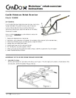
1. As shown in Figure 10-11, the wheel lock handle attaches to the wheel lock handle base with two Allen screws. There
is only one hole in the wheel lock handle base through which to attach the upper Allen screw. There are three holes in
the wheel lock handle base through which to attach the lower Allen screw.
2. Remove the lower Allen screw and locknut that secure the wheel lock handle to the wheel lock handle base.
3. Loosen, but do not remove, the upper Allen screw that secures the wheel lock handle to the wheel lock handle base.
4. Reposition the wheel lock handle to the desired Standard Handle Position 1, 2 or 3 (see Figures 10-7 and 10-8) and
replace the Allen screw and locknut.
5. Securely tighten both Allen screws and locknuts.
Figure 10-11
Removing the Wheel Lock Handle
Allen
Screws
Handle
Base
Locknuts
Reversed Handle Positions 1, 2, 3
You can achieve three additional wheel lock handle positions for your Uni-Lock by reversing the wheel lock handles from
the right and left Uni-Locks. To do this, follow the procedures below.
Tools Needed:
• 1/8” Allen Wrench
• 3/8” Open End Wrench
1. Remove the two Allen screws and locknuts that secure the wheel lock handle to the wheel lock handle base on both the
right and left Uni-locks. See Figure 10-11.
2. Install the wheel lock handle from the left Uni-Lock on the right Uni-Lock in the desired position. See Figures 10-9 and
10-10.
3. Install the wheel lock handle from the right Uni-Lock on the left Uni-Lock.
4. Securely tighten all screws and locknuts.
Uni-Lock with Extension Handles
All of the adjustments set forth under “Uni-Lock” on pages 10-2 to 10-5 apply to the Uni-Lock with Extension Handles.
Compact Scissor Lock
Adjusting
Tools Needed:
• 3/16” Allen Wrench
1. Loosen, but do not remove, the two Allen screws in the wheel lock clamp. See Figure 10-12.
2. Adjust the position of the wheel lock clamp on the frame so the wheel stop embeds at least 3/16” into the tire when
engaged in the locked position.
3. Securely tighten the two Allen screws that secure the wheel lock clamp to the frame.