background image


  Thermo Scientific AquaSensors

 DataStick

 Ethernet Communications User Guide 

69


7.2.4  Example SLC 5/05 Ladder Logic Programs 

The ladder logic programs for a SLC 5/05 are very similar to the ladder logic programs 
shown in Section 7.2.2, Example SLC 5/03 Ladder Logic Programs.  The main difference 
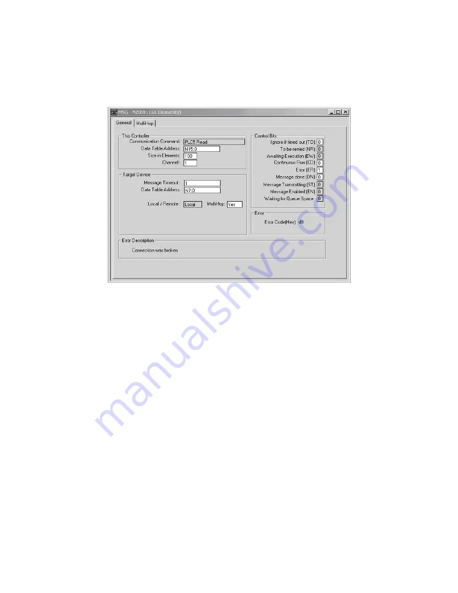
is in the Setup screen for the MSG instruction as shown in Figure 65. 


Figure 65:  The Setup screen for a MSG instruction in a SLC 5/05 PLC. 

Summary of Contents for AquaSensors AV38

Page 1: ...Thermo Scientific AquaSensors AV38 and DataStick Ethernet Communications User Guide ...

Page 2: ...nk ROSS Resolution SAOB SMART AVERAGING Smart CheK SMART STABILITY Stacked Star Navigator 21 Stat Face The Enhanced Lab ThermaSense Triode TRIUMpH Unbreakable pH Universal Access are trademarks of Thermo Fisher Guaranteed Success and The Technical Edge are service marks of Thermo Fisher PerpHecT meters are protected by U S patent 6 168 707 PerpHecT ROSS electrodes are protected by U S patent 6 168...

Page 3: ...5 1 Home Page 37 5 2 Calibration Page 38 5 3 Configuration Page 39 5 4 Communications Settings Page 41 5 4 1 Viewing Changing the Communications Settings 41 5 4 2 Viewing Clearing the Internal Counters 41 5 4 3 Upgrading the Firmware 42 6 EtherNet IP 43 6 1 Electronic Data Sheet EDS 43 6 2 Definitions 43 6 3 Reference Documents 43 6 4 Open DeviceNet Vendor Association Inc ODVA 44 6 5 Object Model ...

Page 4: ...TCP and PCCC 54 7 1 Modbus TCP 54 7 1 1 Modbus TCP Reference 55 7 2 Programmable Controller Communication Commands PCCC 55 7 2 1 SLC 5 03 and SLC 5 04 PLCs 56 7 2 2 Example SLC 5 03 Ladder Logic Programs 58 7 2 3 SLC 5 05 PLC 68 7 2 4 Example SLC 5 05 Ladder Logic Programs 69 7 2 5 PCCC References 70 7 3 Modbus TCP and PCCC Register Map 71 8 Certifications 82 9 General References 82 10 Limited War...

Page 5: ... right hand corner of the overlay 15 Figure 16 Restoring default communications settings of an Adapter embedded inside an AV38 16 Figure 17 A power injector 19 Figure 18 An Ethernet DataStick network for evaluation or demonstration purposes 19 Figure 19 An AV38 network for evaluation or demonstration purposes 20 Figure 20 Network Connections window 20 Figure 21 Local Area Connection Properties 21 ...

Page 6: ... 58 Figure 53 The Message Routing tab of the ENI Configuration Utility 59 Figure 54 Part 1 of 3 of a ladder logic program that reads the Sensor Value from N20 01 60 Figure 55 Part 2 of 3 of a ladder logic program that reads the Sensor Value from N20 01 61 Figure 56 Part 3 of 3 of a ladder logic program that reads the Sensor Value from N20 01 62 Figure 57 The Setup screen for a MSG instruction in a...

Page 7: ...00 information registers 80 Table 10 Register bank 6000 AV38 configuration register 81 Contact Information To contact Thermo Scientific AquaSensors Technical Support Within the United States call 1 800 225 1480 or fax 978 232 6015 Outside the United States call 978 232 6000 or fax 978 232 6031 In Europe the Middle East and Africa contact your local authorized dealer Visit us on the web at www ther...

Page 8: ...ted AV38 network 1 Change the computer s IP address to 192 168 0 1 2 Plug the product into the PoE side of the power injector 3 Connect the power injector to the computer using a CAT5 cross over cable 4 Point your Web browser at 192 168 0 100 to see the Home Page The Home Page will show the product s measurement values configuration and diagnostic information From there the product s IP address ca...

Page 9: ...in Figure 3 that is plugged into the DataStick Body Figure 3 The Ethernet Communications Adapter The second form is as an option in the AV38 Local Display as shown in Figure 4 Figure 4 The Ethernet option in the AV38 Local Display front and rear views The product provides full featured measurement configuration calibration and diagnostics of any DataStick measurement system from any Ethernet enabl...

Page 10: ...here are red and green LED indicators on this end of the Adapter that make it easy to know when the Ethernet link is active The cable can be up to 100 meters 328 feet long although we recommend that the Adapter be ordered with 10 30 feet of cable to reduce cost When plugged into a DataStick sensor system the Adapter becomes an integral part of the measurement system and the system can be mounted a...

Page 11: ... option in the AV38 For information about the rest of the AV38 please see the AV38 User s Manual 3 Hardware Setup Both forms of the product possess the same default communications settings They are as follows IP Address 192 168 0 100 Subnet Mask 255 255 255 0 Gateway Address 192 168 0 1 Both forms support a data rate of 10 Mbps 10Base T Both forms comply with the IEEE 802 3af Power Over Ethernet s...

Page 12: ...er Scientific Figure 9 The three parts of the DataStick measurement system The Adapter can be removed and replaced in the field This may be desirable for any number of reasons some of which are Ethernet Diagnostics Observe the Link Activity LED to confirm the communications link DataStick Diagnostics Temporarily plug in a USB Communications Adapter for PC diagnostics Repair Replace a damaged DataS...

Page 13: ...ighten the retaining ring with a 15 16 inch wrench It is very important to tighten the retaining ring to ensure a reliable connection The different parts of the Adapter are shown in Figure 11 Figure 11 The different parts of the Adapter 3 1 1 Operating Temperature While operating at room temperature 22 C or 72 F the Adapter runs at around body temperature 37 C or 99 F This is normal ETHERNET ADAPT...

Page 14: ... RJ45 connector pin assignment Pin Position Signal Name Function Mode A Signal Name Function Mode B 1 Tx Transmit DC Tx Transmit 2 Tx Transmit DC Tx Transmit 3 Rx Receive DC Rx Receive 4 Not used DC 5 Not used DC 6 Rx Receive DC Rx Receive 7 Not used DC 8 Not used DC 3 1 3 Location of Adapter s MAC Address The Adapter s Media Access Control MAC Address is printed on a label that is affixed to the ...

Page 15: ...ty LED glows green when there is a link between the Adapter and another network device and it glows red when there is network activity The Heartbeat LED is recessed within the body of the Adapter It blinks green at a rate of 1 Hz while the Adapter is operating normally It blinks red and green to indicate that the IP Address Subnet Mask and Gateway Address have been restored to default values See S...

Page 16: ... between pins 5 and 9 on the DataStick side of the Adapter using a clip lead or equivalent as shown in Figure 14 Be careful to make the connection only between pins 5 and 9 4 Apply power to the Adapter and watch the Heartbeat LED shown in Figure 14 After approximately 5 seconds the Heartbeat LED will blink red and green at a rate of 2 Hz This indicates that the Adapter has detected the connection ...

Page 17: ...al names and functions Position Signal Name Function Mode A Signal Name Function Mode B 1 Tx Transmit DC Tx Transmit 2 Tx Transmit DC Tx Transmit 3 Rx Receive DC Rx Receive 4 Not used DC 5 Not used DC 6 Rx Receive DC Rx Receive 7 Not used DC 8 Not used DC 3 2 2 Location of AV38 s MAC Address The AV38 s Media Access Control MAC Address is printed on a label that is affixed to the terminal block ove...

Page 18: ...ork Attention Determine how your control system will respond before disconnecting an AV38 2 Remove the terminal block overlay 3 Make an electrical connection between the two test points on the terminal board of the AV38 using a clip lead or equivalent The test points are circled in white in Figure 16 4 Reconnect the AV38 to the Ethernet network and wait at least 60 seconds for the communications s...

Page 19: ... The default static IP address for Thermo Scientific AquaSensors Ethernet products is provided on a paper tag for initial access and setup When connecting to a network be sure to configure an IP address that will not be in conflict with other devices or DHCP servers on the network If there is an IP address conflict several devices on the network may not communicate Note It is important to tag Ther...

Page 20: ...ing a product that s to be put into service There are many ways to connect a product to a computer so that it can be configured This section describes three 1 Using a power injector and a CAT5 cross over cable 2 Using an Ethernet hub or switch and a CAT5 patch cable 3 Using an 802 3af compliant PoE Ethernet hub or switch and a CAT5 patch cable Choose the way that is most convenient for you Attenti...

Page 21: ...s conflict This connection method is also convenient for evaluating or demonstrating a DataStick measurement system To set up the network you will need the following a computer with a Web browser and an Ethernet port an Ethernet DataStick or an AV38 with Ethernet option a CAT5 cross over cable a power injector such as the one shown in Figure 17 Figure 17 A power injector An Ethernet DataStick netw...

Page 22: ...s settings haven t been changed since the product was received from Thermo Fisher Scientific then this step can be skipped The next step is to change the IP address of the laptop to 192 168 0 1 so that it can communicate with the product Follow the procedure below to accomplish this Attention If the laptop is connected to a network disconnect the laptop before continuing This will avoid any potent...

Page 23: ...es This will bring up the Local Area Connection Properties as shown in Figure 21 Figure 21 Local Area Connection Properties Highlight Internet Protocol TCP IP and click the Properties button This will bring up the Internet Protocol TCP IP Properties window as shown in Figure 22 Figure 22 The Internet Protocol TCP IP Properties window ...

Page 24: ...w the procedure below to accomplish this Connect the power injector to the laptop using the CAT5 cross over cable Be careful not to plug the cross over cable into the jack that has the DC power on it This jack is typically identified with a warning sticker that says Connect to PoE device only Connect the Ethernet DataStick to the power injector by plugging the Ethernet DataStick s integral CAT5 ca...

Page 25: ...ies window has an Alternate Configuration tab as shown in Figure 25 then the laptop can be configured so that it will obtain an IP address automatically when one is available or it will use a static IP address when one is not This advanced configuration makes moving from a home office network environment to an isolated network environment a little easier On the General tab of the Internet Protocol...

Page 26: ...ab click the User configured radio button and enter the values shown in Figure 26 Figure 26 The alternate configuration settings Click OK until you return to the Network Connections window The laptop can now be connected to a home office network where it will obtain an IP address automatically or to an Ethernet DataStick where it will use a static IP address ...

Page 27: ... computer that s connected to the destination network as shown in Figure 27 To open a Command Prompt click Start Run and type cmd in the Open field Figure 27 The output of the ipconfig command To determine the network s subnet bitwise AND the IP address with the subnet mask In the example of Figure 27 the IP address is 192 168 10 107 and the subnet mask is 255 255 255 0 192 168 10 107 bitwise ANDe...

Page 28: ...an Ethernet DataStick and the IP address of the computer must be changed so it can communicate with the DataStick Follow the procedure below to accomplish this Windows xp is used but Windows 2000 and Vista as well as other operating systems will also work An isolated network can be constructed in several different ways depending upon the equipment that s available If you have the following equipme...

Page 29: ...ng equipment Ethernet hub or switch CAT5 patch cable then a network like the one shown in Figure 30 or Figure 31 can be constructed Figure 30 An Ethernet DataStick network constructed with an Ethernet switch and patch cables Figure 31 An AV38 network constructed with an Ethernet switch and patch cables ...

Page 30: ... a network like the one shown in Figure 32 or Figure 33 can be constructed Figure 32 An Ethernet DataStick network constructed with a PoE switch and a patch cable Figure 33 An AV38 network constructed with a PoE switch and patch cables Now that an isolated network has been constructed it s time to change the IP address of the computer so that it can communicate with the DataStick ...

Page 31: ...clicking Start Control Panel Network Connections Figure 34 Network Connections window Right click on Local Area Connection and select Properties This will bring up the Local Area Connection Properties window as shown in Figure 35 Figure 35 Local Area Connection Properties Highlight Internet Protocol TCP IP and click the Properties button ...

Page 32: ...he Internet Protocol TCP IP Properties window Click the Use the following IP address radio button and enter the IP address Subnet mask and Default gateway values as shown in Figure 37 Figure 37 Giving the computer a static IP address Click OK until you return to the Network Connections window The computer now has a static IP address of 192 168 0 1 and its subnet is 192 168 0 0 ...

Page 33: ...f IP addresses controlled by the DHCP server This will avoid potential conflicts between the Ethernet DataStick and any devices that might be added to the network at a later time Before settling on the candidate address for the Ethernet DataStick use the ping utility to verify that there is not already a device at that address Figure 38 shows the output of the ping command that was run on a comput...

Page 34: ...Stick Ethernet Communications User Guide 32 Start a Web browser on the computer and enter 192 168 0 100 in the Address field This will bring up the DataStick s Home Page as shown in Figure 39 Figure 39 The Ethernet DataStick s Home Page ...

Page 35: ...AquaSensors DataStick Ethernet Communications User Guide 33 Click on the CommSettings button to access the communications settings The IP Setup Page will appear as shown in Figure 40 Figure 40 The product s IP Setup Page ...

Page 36: ...nsors DataStick Ethernet Communications User Guide 34 Click the Edit button and enter the following information User name aqa Password aqa as shown in Figure 41 Figure 41 Entering the username and password in the IP Setup Page ...

Page 37: ...is example the desired IP address is 192 168 10 200 as shown in Figure 42 Figure 42 The IP address subnet mask and gateway address edited as desired After the values have been edited as desired click the Apply button To abort this step click the Cancel button The IP Address Subnet Mask and Default Gateway will be returned to their previous values ...

Page 38: ...ng and reconnecting the product s Ethernet connection Enter the product s new IP address in the Address field of the Web browser to bring up the Home Page as shown in Figure 43 Figure 43 The Home Page as seen from the Product s new IP address The Ethernet DataStick s communications settings have now been set as desired and it can be connected to the desired network This completes the configuration...

Page 39: ... for all measurement types in the center column and diagnostic information in the right column It is updated automatically every 20 seconds and can be refreshed manually at any time In the lower left corner are buttons for viewing changing the communications settings and a link to the Thermo Fisher Scientific Website The I O Status field is an indication of the status of the communications between...

Page 40: ... Type field will indicate No Sensor 5 2 Calibration Page The calibration page can be accessed by clicking on the Sensor or Temperature Value on the Home Page as shown in Figure 45 Figure 45 Accessing the Calibration Page The calibration page as shown in Figure 46 allows a 1 point sample calibration to be done on the DataStick Figure 46 The DataStick Measurement System Calibration Page Click on the...

Page 41: ...e and the Last Cal Type and Calibration Status fields Calibration Status will indicate Cal OK if the procedure completed successfully Clicking the Cancel button instead of the Set button will return the 1 Point Sample Calibration value to its previous value 5 3 Configuration Page The configuration edit page can be accessed by clicking on any of the Measurement Units or Configuration Values on the ...

Page 42: ...d Figure 48 The Configuration Edit Page To change the configuration of the DataStick enter the desired value in the editable field and click on the corresponding Set button For more information about re configuring a DataStick see the DataStick Manual Clicking the Cancel button instead of the Set button will return the Configuration Setting to its previous value ...

Page 43: ...tions settings page allows the network settings to be viewed changed some counters internal to the Ethernet product to be viewed cleared the firmware in the Ethernet product to be upgraded 5 4 1 Viewing Changing the Communications Settings See Section 4 Configuration Procedures for more information about changing the communications settings 5 4 2 Viewing Clearing the Internal Counters There are fo...

Page 44: ...requesting it The Write Errors counter is incremented every time the Ethernet product receives an error while trying to write to the DataStick It is a count of the total number of write errors for all of the protocols supported For instance if an attempt is made to change the Sensor Filter value to 200 using the Web Server s Configuration Page the DataStick will respond with an error because the l...

Page 45: ... Be sure to register the EDS file with the configuration tool that you will be using 6 2 Definitions Network Client The EtherNet IP network host commonly a scanner module in a programmable logic controller Network Server An EtherNet IP device that implements server functionality in an EtherNet IP system Programmable Logic Controller PLC refers to the EtherNet IP network host BYTE An unsigned 8 bit...

Page 46: ... created Table 3 These objects are identical in the Ethernet products and DeviceNet Adapter object models Object Name System Status Sensor Installation Sensor Value User Configuration Generic Sensor Calibration Conductivity Sensor Calibration Mode Configuration For a detailed explanation of the Instance Attributes please see the description of the associated Thermo Scientific AquaSensors Command i...

Page 47: ... Get_Attribute_Single 05HEX No Yes Reset 6 5 3 Message Router Object 02HEX 0 Instances No attributes or services supported 6 5 4 Assembly Object 04HEX 2 Instances 6 5 4 1 Class Attributes Attribute ID Name EtherNet IP Data Type Data Value Access Rule 1 Revision UINT 2 Get 2 Max Instance UINT 130 Get 6 5 4 2 Instance 100 64 hex Attributes Input Instance Attribute ID Name EtherNet IP Data Type Defau...

Page 48: ...tion Instance supports 0 400 bytes of data If no configuration data is needed this instance may be omitted 6 5 4 6 Common Services Implemented for Service Code Class Level Instance Level Service Name 0EHEX Yes Yes Get_Attribute_Single 10HEX No Yes Set_Attribute_Single 6 5 5 Connection Manager Object 06HEX This object has no attributes 6 5 6 TCP Object F5HEX 1 Instance 6 5 6 1 Class Attributes Attr...

Page 49: ...ttribute ID Name Data Type Default Data Value Access Rule 1 Interface Speed 7 UDINT 10 Get 2 Interface Flags 8 DWORD 3 Get 3 Physical Address 9 USINT Array 6 0 Get 1 See section 5 3 2 2 1 of Volume 2 EtherNet IP Adaptation of CIP from ODVA for more details on this attribute 2 See section 5 3 2 2 2 of Volume 2 EtherNet IP Adaptation of CIP from ODVA for more details on this attribute 3 See section ...

Page 50: ...t The Writes Pending is incremented every time the Ethernet product has been asked to write to the DataStick but has not yet completed the operation The count is decremented each time a write completes The Read Error Count is incremented every time the Ethernet product receives an error while trying to read from the DataStick Body It is a count of the total number of read errors for all of the pro...

Page 51: ... UINT 0 Get 101 Writes Pending N A N A UINT 0 Get 102 Read Error Count N A N A UINT 0 Get Set 10 103 Write Error Count N A N A UINT 0 Get Set 10 104 Timeout Count N A N A UINT 0 Get Set 10 6 5 8 3 Common Services Implemented for Service Code Class Level Instance Level Service Name 0EHEX Yes Yes Get Attribute Single 6 5 9 Sensor Installation Object 65HEX 1 Instance 6 5 9 1 Class Attributes Attribut...

Page 52: ...UINT 1 Get 6 5 10 2 Instance Attributes Attribute ID Name Thermo Scientific AquaSensors Command Thermo Scientific AquaSensors Offset EtherNet IP Data Type Default Data Value Access Rule 1 Sensor Value GSNSR 0 REAL NAN Get 2 Temperature Value GTEMP 0 REAL NAN Get 6 5 10 3 Common Services Implemented for Service Code Class Level Instance Level Service Name 0EHEX Yes Yes Get Attribute Single 6 5 11 U...

Page 53: ...et 9 DO Pressure GPRESS SPRESS 0 REAL NAN Get Set 10 Conductivity Reference Temperature GCRTEMP SCRTEMP 0 REAL NAN Get Set 11 Conductivity Compensation Slope GCCSLOPE SCCSLOPE 0 REAL NAN Get Set 12 Node Address GADDR SADDR 0 USINT 0 Get Set 13 DataStick Address GDSA SDSA 0 UINT 0 Get Set 14 DataStick Timeout 2 to 200 10 msec tick NA NA UINT 0 Get Set 15 TDS Conversion Factor GTDSF STDSF 0 REAL NAN...

Page 54: ...REAL NAN Get Set 11 9 Calibration Type CALSTATUS 3 UINT 0 Get 10 Calibration Status CALSTATUS 6 UINT 0 Get 11 Calibration Abort CALABORT N A None 0 Get Set 11 6 5 12 3 Common Services Implemented for Service Code Class Level Instance Level Service Name 0EHEX Yes No Get Attribute Single 10HEX No Yes Set Attribute Single 6 5 13 Conductivity Sensor Calibration Object 69HEX 1 Instance 6 5 13 1 Class A...

Page 55: ...ess Rule 2 PLC Data Type format of Implicit data object N A N A USINT 0 Get Set 6 5 14 3 PLC Data Type Value Type 0 Little Endian ControlLogix 1 Little Endian Word Swap SLC 2 Big Endian 3 Big Endian Word Swap 6 5 14 4 Common Services Implemented for Service Code Class Level Instance Level Service Name 0EHEX Yes Yes Get Attribute Single 10HEX No Yes Set Attribute Single Please note that the PLC Dat...

Page 56: ...f the Internet and is actually a set of layered protocols providing a reliable data transport mechanism between machines Ethernet has become the de facto standard of corporate enterprise systems so it comes as no surprise that it has also become the de facto standard for factory networking Ethernet is not a new technology It has matured to the point that the cost of implementing this network solut...

Page 57: ...et product using an Allen Bradley SLC 5 03 SLC 5 04 or SLC 5 05 PLC using Programmable Controller Communication Commands PCCC The Ethernet product server mimics the behavior of a PLC5 in order to enable communications with a PLC5 SLC 5 03 SLC 5 04 or SLC 5 05 PLC client The PCCC object in the Ethernet product is accessed remotely using explicit messaging via EtherNet IP In order to read registers ...

Page 58: ...words transferred using PCCC For a detailed explanation of the PCCC register contents please see the description of the associated DataStick Command in the DataStick Measurement System Instruction Manual Catalog Number MAN011DS 4 7 2 1 SLC 5 03 and SLC 5 04 PLCs If you have an Allen Bradley SLC 5 03 or SLC 5 04 PLC and wish to communicate with an Ethernet Communications product you ll need a 1761 ...

Page 59: ...I Configuration Utility shown in Figure 51 It can be downloaded from http www ab com programmablecontrol plc micrologix1000 get ENIutility exe Figure 51 The ENI Configuration Utility See the 1761 NET ENI MicroLogix Ethernet Interface User Manual for a complete description of how to configure the ENI ...

Page 60: ...e Com Port Redirector configured to redirect COM32 on the computer to the ENI at IP address 192 168 10 60 port 10 001 The ENI Utility is configured to communicate with the ENI via COM32 Figure 52 The Com Port Redirector Com Port Redirector creates a virtual COM port at COM32 and redirects any communications with COM32 to IP address 192 168 10 60 port 10 001 7 2 2 Example SLC 5 03 Ladder Logic Prog...

Page 61: ...mmunicate with an Ethernet product through an ENI configured as shown in Figure 53 Figure 53 The Message Routing tab of the ENI Configuration Utility When a MSG instruction from the PLC with a Local Node Address Destn of 9 arrives at the RS 232 port on the ENI the ENI routes it to the Ethernet product at IP address 192 168 10 201 ...

Page 62: ...1 using a Message MSG instruction and stores it in F8 0 in the PLC Note that on rung 3 the two words that make up the floating point Sensor Value are swapped before they re copied to the F8 file The program is event driven in that the completion of a MSG instruction triggers the transmission of another one A count of the messages sent is kept as well as a count of any errors that may have occurred...

Page 63: ...munications User Guide 61 Figure 55 Part 2 of 3 of a ladder logic program that reads the Sensor Value from N20 01 In the MSG instruction on rung 3 note that the Type is Peer to Peer and that it is a Read instruction The Target Device must be set to PLC5 ...

Page 64: ...LC where the Sensor Value is to be stored Note that the Size in Elements is 2 because Sensor Value is a floating point data type that occupies registers N20 01 and N20 02 in the Ethernet product The Channel is 0 because this is the RS 232 port on the SLC to which the ENI is connected Figure 57 The Setup screen for a MSG instruction in a SLC 5 03 The source information is shown in the Target Device...

Page 65: ...Thermo Scientific AquaSensors DataStick Ethernet Communications User Guide 63 Figure 58 shows the Sensor Value 7 pH that was read from N20 01 and stored in F8 0 Figure 58 The Sensor Value in F8 0 ...

Page 66: ... 192 168 10 201 using a Message MSG instruction and stores it in N7 0 in the PLC It also writes the value in N7 10 in the PLC to N30 18 in the Ethernet product when bit B3 0 1 is toggled The program is event driven in that the completion of a MSG instruction triggers the transmission of another one A count of the messages sent is kept as well as a count of any errors that may have occurred Figure ...

Page 67: ...AquaSensors DataStick Ethernet Communications User Guide 65 Figure 60 Part 2 of 3 of a ladder logic program to read and write the Sensor Filter value at N30 18 Note that the type of the MSG instruction on rung 6 is Write ...

Page 68: ...s DataStick Ethernet Communications User Guide 66 Figure 61 Part 3 of 3 of a ladder logic program to read and write the Sensor Filter value at N30 18 This program can easily be extended to read and write other configuration values ...

Page 69: ...Sensor Filter value is an integer data type that occupies register N30 18 in the Ethernet product The Channel is 0 because this is the RS 232 port on the SLC to which the ENI is connected Figure 62 The Setup screen for a MSG instruction in a SLC 5 03 The destination information is shown in the Target Device field The Message Timeout specifies the amount of time that the MSG instruction will wait f...

Page 70: ... changed to 1 The figure also shows the MESSAGES_SENT_COUNT in N7 100 and the ERROR_COUNT in N7 101 Figure 63 The N7 register showing the Sensor Filter value and the new Sensor Filter value 7 2 3 SLC 5 05 PLC A SLC 5 05 PLC can be connected directly to an Ethernet network no intermediate equipment is required Figure 64 shows a SLC 5 05 connected directly to an Ethernet network Figure 64 SLC 5 05 P...

Page 71: ... Programs The ladder logic programs for a SLC 5 05 are very similar to the ladder logic programs shown in Section 7 2 2 Example SLC 5 03 Ladder Logic Programs The main difference is in the Setup screen for the MSG instruction as shown in Figure 65 Figure 65 The Setup screen for a MSG instruction in a SLC 5 05 PLC ...

Page 72: ...ifying the IP address of the Ethernet product on the Setup screen of the SLC 5 05 MSG instruction Also the Channel must be set to 1 instead of 0 so that the MSG instruction will be sent out the Ethernet port instead of the RS 232 port 7 2 5 PCCC References 1761 NET ENI MicroLogix Ethernet Interface User Manual Publication 1761 UM006E EN P http literature rockwellautomation com idc groups literatur...

Page 73: ...s section each row contains two entries in the Register Number column the top entry is the Modbus TCP register and the bottom entry is the PCCC register as shown in Figure 67 Both represent the same register in the Ethernet product Figure 67 The top entry is the Modbus TCP register and the bottom entry is the PCCC register The Uptime registers shown in Table 4 indicate the elapsed time since the p...

Page 74: ...00 contain floating point values Use these registers if the other devices on the network support floating point values If the other devices on the network do not support floating point values corresponding integer values can be found in Bank 3000 If the product is not attached to a DataStick body the Sensor Value float and the Temperature Value float shown in Table 6 will read Not a Number NaN Tab...

Page 75: ...2 016 N20 16 42 017 N20 17 42 018 N20 18 42 019 N20 19 42 020 N20 20 42 021 N20 21 42 022 N20 22 42 023 N20 23 DO Salinity float R W GSALT SSALT 232 1 Configuration 42 024 N20 24 42 025 N20 25 DO Pressure float R W GPRESS SPRESS 764 2 Configuration 42 026 N20 26 42 027 N20 27 Conductivity Reference Temperature float R W GCRTEMP SCRTEMP 25 1 Configuration 42 028 N20 28 42 029 N20 29 Conductivity Co...

Page 76: ...400 00 mV At a resolution of 0 01 mV the corresponding integer value would be 400 000 which would exceed the register s ability to represent it In this case the resolution is decreased to 0 1 mV the corresponding scale factor becomes 10 and the integer value becomes 4 000 which is representable When calibrating the DataStick system use the primary units of measure e g calibrate pH in pH not in mV ...

Page 77: ...t integer R W CALABORT No DS arguments N A Calibration 43 012 N30 12 DO Salinity integer R W GSALT SSALT 2321 Configuration 43 013 N30 13 DO Pressure integer R W GPRESS SPRESS 7642 Configuration 43 014 N30 14 Conductivity Reference Temperature integer R W GCRTEMP SCRTEMP 251 Configuration 43 015 N30 15 Conductivity Compensation Slope integer R W GCCSLOPE SCCSLOPE 201 Configuration 43 016 N30 16 Ce...

Page 78: ...0 25 PLC Data Type integer R W N A Big Endian 1 Configuration 43 026 N30 26 Timeout integer R W N A ms 500 Configuration 43 027 N30 27 43 028 N30 28 TDS Conversion Factor integer R W GTDSF STDSF 49 Configuration 43 029 N30 29 43 030 N30 30 MAC Address integer R W N A Writable only Configuration 43 031 N30 31 integer R W N A if 0 Configuration 43 032 N30 32 integer R W N A Configuration ...

Page 79: ...d on the type of Sensor Head installed in the DataStick The Sensor Value Scale Factor is one of these For example when the installed Sensor Head is pH the Sensor Value Scale Factor is 100 but when the installed Sensor Head is ORP the Sensor Value Scale Factor is 1 Table 8 Register bank 4000 integer scale factor registers Register Number Description Data Type Access DataStick Command Comment Exampl...

Page 80: ...cale Factor 44 017 N40 17 44 018 N40 18 44 019 N40 19 44 020 N40 20 44 021 N40 21 44 022 N40 22 44 023 N40 23 44 024 N40 24 44 025 N40 25 44 026 N40 26 44 027 N40 27 44 028 N40 28 TDS Conversion Factor S F integer R N A fixed 100 Scale Factor 44 029 N40 29 When power is applied to the Ethernet product it takes a short amount of time for it to update its local copy of the data stored in the DataSti...

Page 81: ...y It is a count of the total number of read errors for all of the protocols supported Some DataStick Body data might not be available depending on the type of Sensor Head installed When the Ethernet product tries to read this unavailable data the DataStick will respond with an error and this will cause the Read Error Count to be incremented The Ethernet product will realize that this data is unava...

Page 82: ...SCII 2 R W Null Null Information 45 009 N50 09 Main Serial Number09 ASCII 2 R W Null Null Information 45 010 N50 10 Main Serial Number10 ASCII 2 R W Null Null Information 45 011 N50 11 Main Serial Number11 ASCII 2 R W Null Null Information 45 012 N50 12 Main Serial Number12 ASCII 2 R W Null Null Information 45 013 N50 13 Main Serial Number13 ASCII 2 R W Null Null Information 45 014 N50 14 Main Ser...

Page 83: ... Information 45 032 N50 32 Location07 ASCII 2 R W N A Information 45 033 N50 33 Location08 ASCII 2 R W N A Information 45 034 N50 34 Data Valid integer R N A Information 45 035 N50 35 Pending Writes integer R N A Information 45 036 N50 36 Read Error Count integer R W N A Resets to 0 on write Information 45 037 N50 37 Write Error Count integer R W N A Resets to 0 on write Information 45 038 N50 38 ...

Page 84: ...Node Device the Modbus IDA Conformance Test Program 9 General References IEEE Standard 802 3 10Base T Ethernet http standards ieee org getieee802 index html IEEE Standard 802 3af Power Over Ethernet http standards ieee org getieee802 index html TIA EIA 568 B Commercial Building Telecommunications Cabling Standard http www tiaonline org DataStick Measurement System Instruction Manual ...

Page 85: ...lication or installation 2 Damage caused by any repair or attempted repair not authorized by Thermo Fisher Scientific 3 Any product not used in accordance with the instructions furnished by Thermo Fisher Scientific 4 Damage caused by acts of God natural disaster acts of war declared or undeclared acts of terrorism work actions or acts of any governmental jurisdiction 5 Freight charges to return me...

Page 86: ... are not valid unless accepted in writing Sales taxes shall be included on the invoice unless a valid tax exemption certificate is supplied Return Material Authorization Contact Thermo Fisher Scientific Customer Service for a Return Material Authorization RMA number Items returned without an RMA number will be rejected All returned merchandise must be in unused resalable condition and must not be ...

Page 87: ......

Page 88: ...000 Dom Fax 1 978 232 6015 Int l Fax 978 232 6031 Europe P O Box 254 3860 AG Nijkerk Wallerstraat 125K 3862 BN Nijkerk Netherlands Tel 31 033 2463887 Fax 31 033 2460832 Asia Pacific Blk 55 Ayer Rajah Crescent 04 16 24 Singapore 139949 Tel 65 6778 6876 Fax 65 6773 0836 www thermo com processwater 2009 Thermo Fisher Scientific Inc All rights reserved 258489 001 Rev A 01 09 ...

Reviews: